CHAPTER 4
Cabling the ERX System
4Terminate the other end in the appropriate network connection.
5Repeat steps
6Repeat steps
![]()
![]() RX
RX
CT3/T3
12
I/O
SMB | TX |
|
TX | RX | Port 0 |
|
| |
| TX | Port 1 |
| RX | |
|
| |
| TX | Port 2 |
| RX | |
|
|
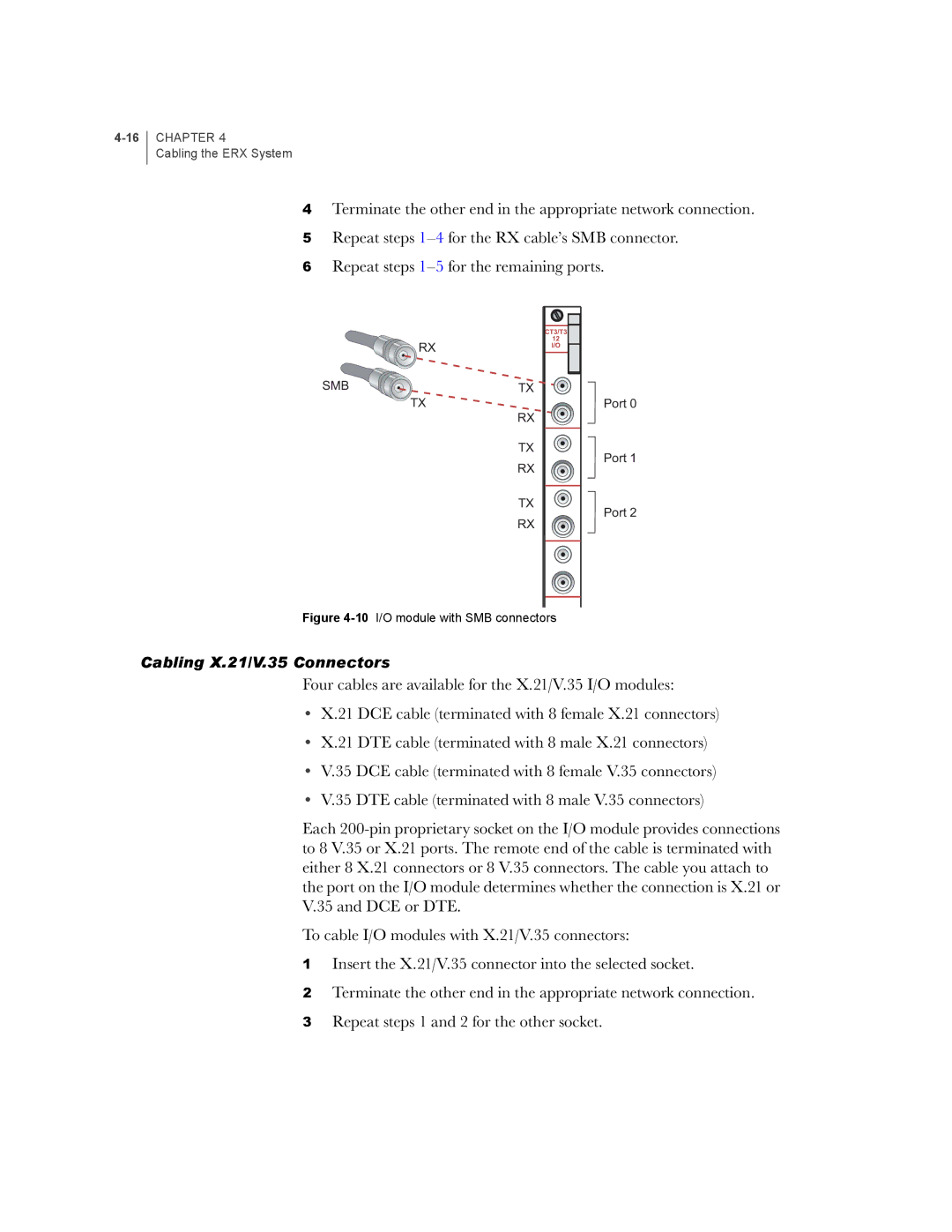
Figure 4-10 I/O module with SMB connectors
Cabling X.21/V.35 Connectors
Four cables are available for the X.21/V.35 I/O modules:
•X.21 DCE cable (terminated with 8 female X.21 connectors)
•X.21 DTE cable (terminated with 8 male X.21 connectors)
•V.35 DCE cable (terminated with 8 female V.35 connectors)
•V.35 DTE cable (terminated with 8 male V.35 connectors)
Each
To cable I/O modules with X.21/V.35 connectors:
1Insert the X.21/V.35 connector into the selected socket.
2Terminate the other end in the appropriate network connection.
3Repeat steps 1 and 2 for the other socket.