CHAPTER 4
Cabling the ERX System
Lightning Activity Warning: Do not work on the system or connect or disconnect cables during lightning activity.
DC Power Disconnection Warning: Before powering on the ERX system, remove power from the DC circuit by deactivating the circuit breaker on the panel board that services the DC circuit.
Servicing Unit Warning: Before servicing the ERX system, turn off the power.
Jewelry Removal Warning: Remove jewelry (including rings, necklaces, and watches) before working on equipment that is connected to power lines. Metal objects heat up when connected to power and ground and can cause serious burns or weld the metal object to the terminals.
Metal Objects Warning: Do not insert any metal object, such as a screwdriver, into an open slot or the backplane. Doing so may cause electric shock and serious burns.
Note: If you plan on using a
Cabling the Power Input Module
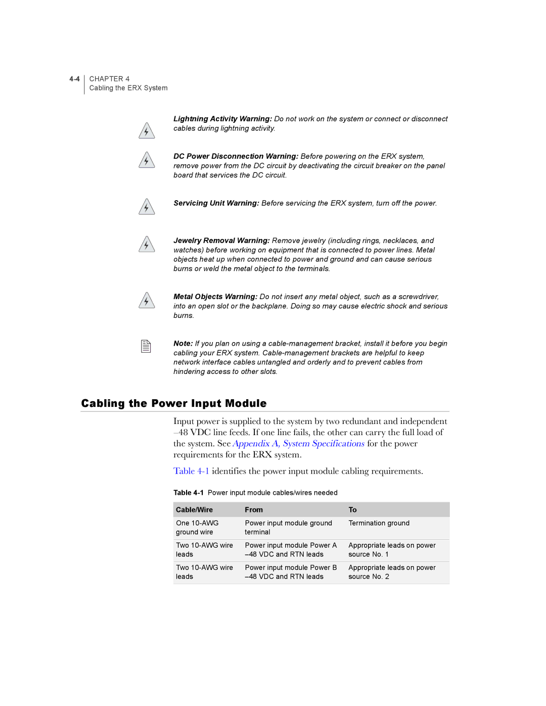
Input power is supplied to the system by two redundant and independent
Table
Table
Cable/Wire | From | To |
One | Power input module ground | Termination ground |
ground wire | terminal |
|
Two | Power input module Power A | Appropriate leads on power |
leads | source No. 1 | |
Two | Power input module Power B | Appropriate leads on power |
leads | source No. 2 | |
|
|
|
