CHAPTER 1
ERX System Overview
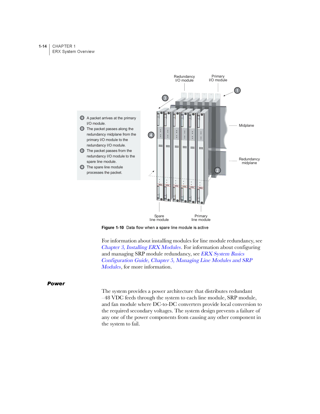
1A packet arrives at the primary I/O module.
2The packet passes along the redundancy midplane from the primary I/O module to the redundancy I/O module.
3The packet passes from the redundancy I/O module to the spare line module.
4The spare line module processes the packet.
Redundancy | Primary |
I/O module | I/O module |
![]()
![]() 1 3
1 3 ![]()
![]()
![]()
![]()
![]()
![]()
Midplane
4
Redundancy
midplane
2
Spare | Primary |
line module | line module |
Figure 1-10 Data flow when a spare line module is active
For information about installing modules for line module redundancy, see Chapter 3, Installing ERX Modules. For information about configuring and managing SRP module redundancy, see ERX System Basics Configuration Guide, Chapter 5, Managing Line Modules and SRP Modules, for more information.
Power
The system provides a power architecture that distributes redundant