CHAPTER 4
Cabling the ERX System
10/100
I/O
![]()
![]()
![]()
![]()
![]() Port 0
Port 0
![]()
![]()
![]() Port 1
Port 1
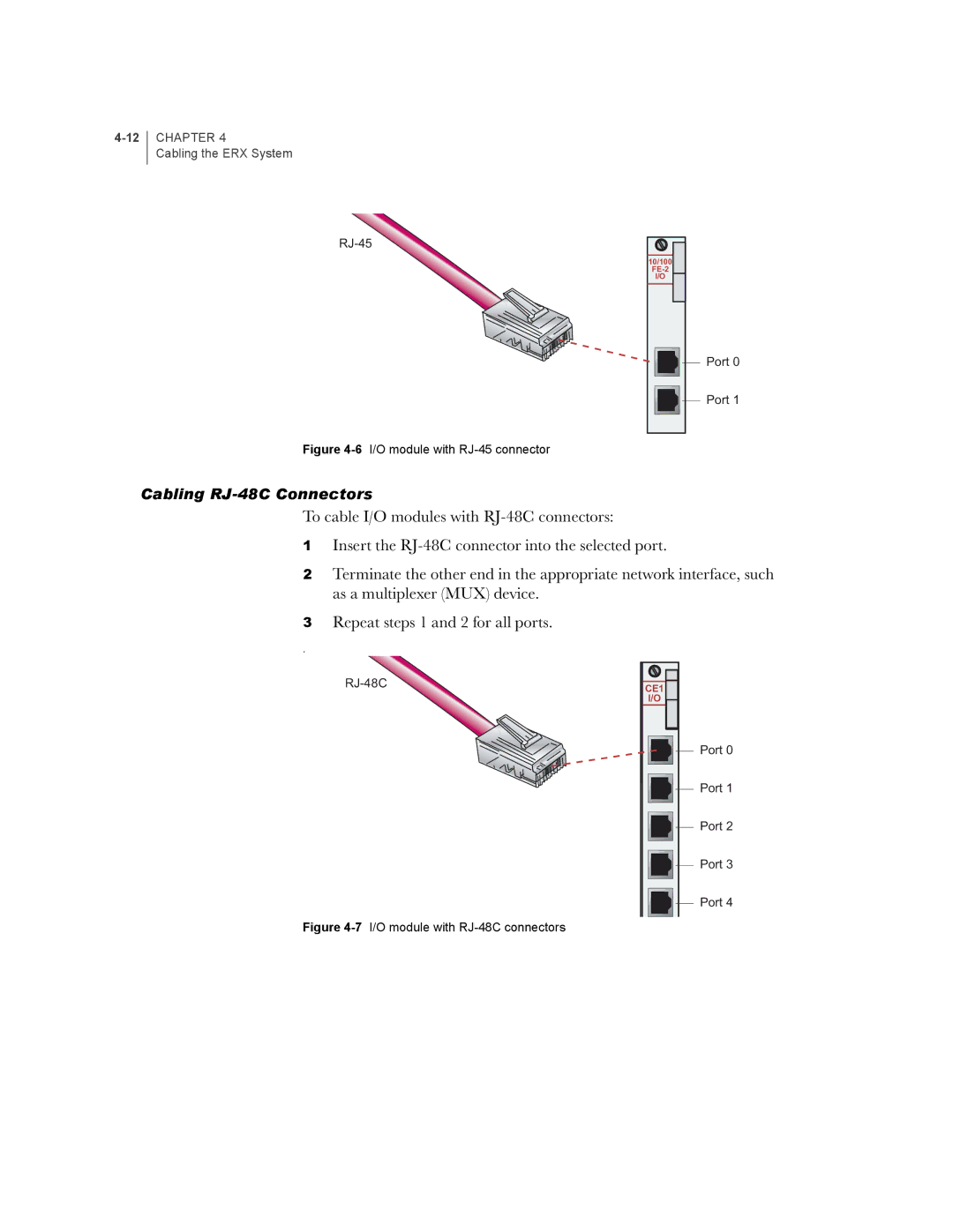
Figure 4-6 I/O module with RJ-45 connector
Cabling RJ-48C Connectors
To cable I/O modules with
1Insert the
2Terminate the other end in the appropriate network interface, such as a multiplexer (MUX) device.
3Repeat steps 1 and 2 for all ports.
.
Figure 4-7 I/O module with RJ-48C connectors
CE1
I/O
![]()
![]()
![]() Port 0
Port 0
![]()
![]()
![]() Port 1
Port 1
![]()
![]()
![]() Port 2
Port 2
![]()
![]()
![]() Port 3
Port 3
![]()
![]()
![]() Port 4
Port 4
