Return to Section TOC
Return to Section TOC
Return to Master TOC
Return to Master TOC
.THEORY OF OPERATION | ||
|
|
|
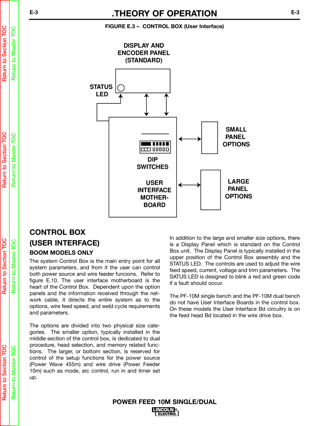
| FIGURE E.3 – CONTROL BOX (User Interface) |
|
DISPLAY AND
ENCODER PANEL
(STANDARD)
STATUS
LED
|
|
|
|
|
|
|
|
|
|
|
|
|
|
|
|
|
| SMALL |
|
|
|
|
|
|
|
|
|
|
|
|
|
|
|
|
|
| |
|
|
|
|
|
|
|
|
|
|
|
|
|
|
|
|
|
| |
|
|
|
|
|
|
|
|
|
|
|
|
|
|
|
|
|
| |
|
|
|
|
|
|
|
|
|
|
|
|
|
|
|
|
|
| |
|
|
|
|
|
|
|
|
|
|
|
|
|
|
|
|
|
| PANEL |
|
|
|
|
|
|
|
|
|
|
|
|
|
|
|
|
|
| |
|
|
|
|
|
|
|
|
|
|
|
|
|
|
|
|
|
| OPTIONS |
|
|
|
|
|
|
|
|
|
|
|
|
|
|
|
|
|
| |
|
|
|
|
|
|
|
|
|
|
|
|
|
|
|
|
|
| |
|
|
|
|
|
|
|
|
|
|
|
|
|
|
|
|
|
|
|
|
|
|
| DIP |
|
|
|
|
|
| ||||||||
|
| SWITCHES |
|
|
|
|
|
| ||||||||||
|
|
|
| USER |
|
|
|
|
| LARGE | ||||||||
|
| INTERFACE |
|
|
|
|
| PANEL | ||||||||||
|
|
| MOTHER- |
|
|
|
|
| OPTIONS | |||||||||
|
|
|
| BOARD |
|
|
|
|
|
| ||||||||
|
|
|
|
|
|
|
|
|
|
|
|
|
|
|
|
|
|
|
|
|
|
|
|
|
|
|
|
|
|
|
|
|
|
|
|
|
|
Return to Section TOC
Return to Section TOC
Return to Master TOC
Return to Master TOC
CONTROL BOX (USER INTERFACE)
BOOM MODELS ONLY
The system Control Box is the main entry point for all system parameters, and from it the user can control both power source and wire feeder funcions. Refer to figure E.10. The user interface motherboard is the heart of the Control Box. Dependent upon the option panels and the information received through the net- work cable, it directs the entire system as to the options, wire feed speed, and weld cycle requirements and parameters.
The options are divided into two physical size cate- gories. The smaller option, typically installed in the middle section of the control box, is dedicated to dual procedure, head selection, and memory related func- tions. The larger, or bottom section, is reserved for control of the setup functions for the power source (Power Wave 455m) and wire drive (Power Feeder 10m) such as mode, arc control, run in and timer set up.
In addition to the large and smaller size options, there is a Display Panel which is standard on the Control Box unit. The Display Panel is typically installed in the upper position of the Control Box assembly and the STATUS LED. The controls are used to adjust the wire feed speed, current, voltage and trim parameters. The SATUS LED is designed to blink a red and green code if a fault should occur.
The