| INSTALLATION | |
|
|
|
Return to Section TOC
Return to Section TOC
Return to Section TOC
Return to Section TOC
Return to Master TOC
Return to Master TOC
Return to Master TOC
Return to Master TOC
EXAMPLES OF CONNECTING AN ARCLINK POWER WAVE SYSTEM
ArcLink Power Wave products may be configured in many different ways. The flexible system allows multi- ple wire feeders to be connected to the same power source. The diagrams represent some of the common methods for connecting ArcLink Products.
Important: Bench model wire feeders cannot be sepa- rated into a separate control box and wire drive for a boom system.
Common ArcLink Systems
The following Power Wave systems may all be assem- bled without any changes to the equipment DIP switch- es
Basic Semi-Automatic System
• Great for general fabrication.
Shown with
•
•
Boom Semi-Automatic System
• Often used when making large weldments.
Shown with
•
•
• Use the bench feeder for offline welding.
Shown with
•
•
•
•
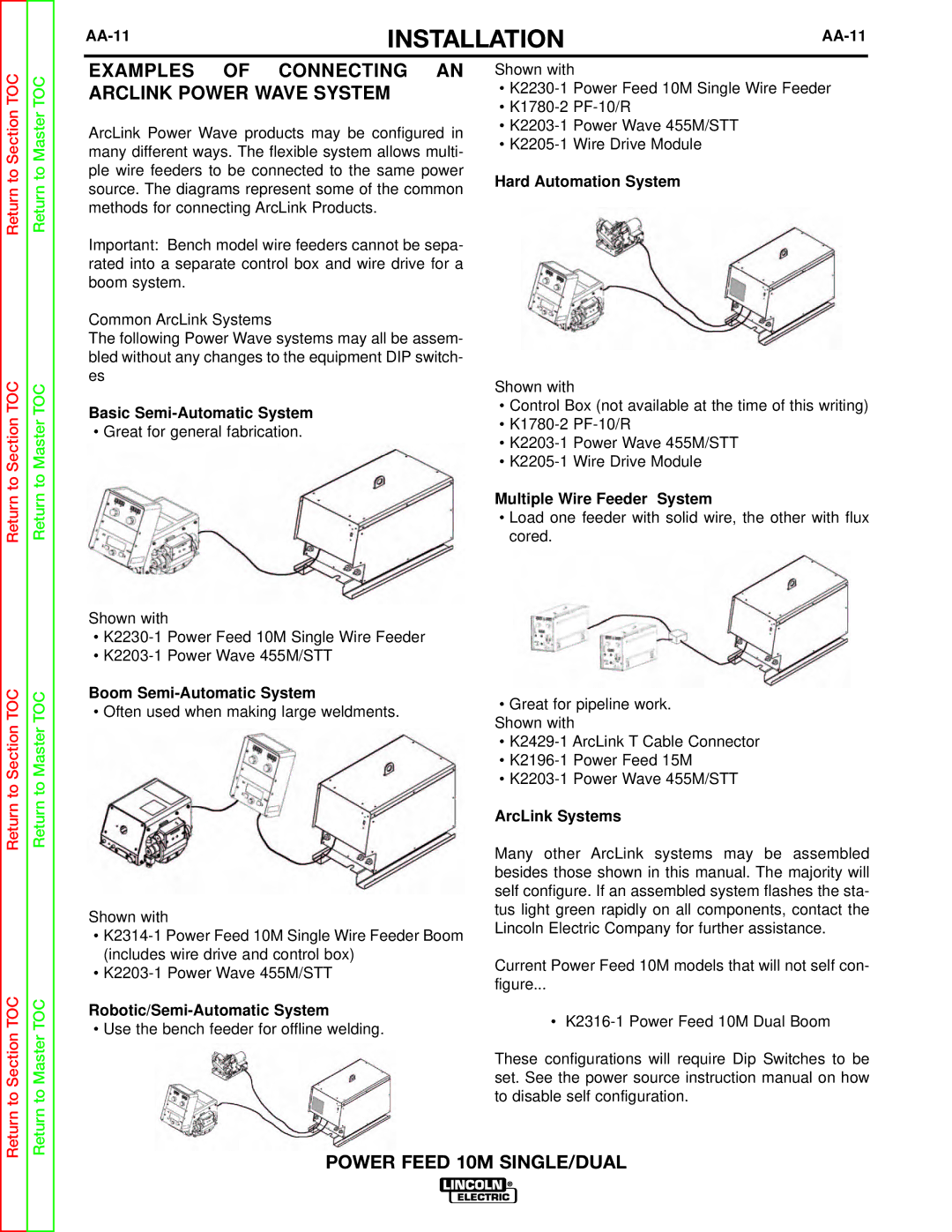
Hard Automation System
Shown with
•Control Box (not available at the time of this writing)
•
•
•
Multiple Wire Feeder System
•Load one feeder with solid wire, the other with flux cored.
•Great for pipeline work. Shown with
•
•
•
ArcLink Systems
Many other ArcLink systems may be assembled besides those shown in this manual. The majority will self configure. If an assembled system flashes the sta- tus light green rapidly on all components, contact the Lincoln Electric Company for further assistance.
Current Power Feed 10M models that will not self con-
figure...
•
These configurations will require Dip Switches to be set. See the power source instruction manual on how to disable self configuration.