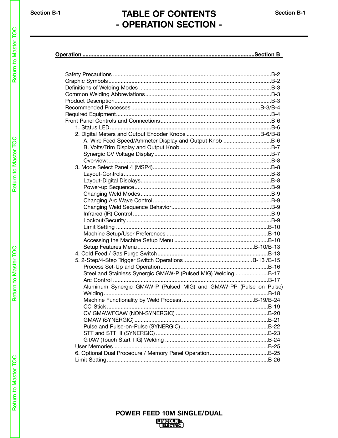
Return to Master TOC
Return to Master TOC
Return to Master TOC
Return to Master TOC
Section | TABLE OF CONTENTS | Section | ||
| - OPERATION SECTION - |
|
| |
|
|
|
| |
| Operation | Section B |
| |
| Safety Precautions | |||
| Graphic Symbols | |||
| Definitions of Welding Modes | |||
| Common Welding Abbreviations | |||
| Product Description | |||
| Recommended Processes |
| ||
| Required Equipment | |||
| Front Panel Controls and Connections | |||
| 1. Status LED | |||
| 2. Digital Meters and Output Encoder Knobs |
| ||
| A. Wire Feed Speed/Ammeter Display and Output Knob | |||
| B. Volts/Trim Display and Output Knob | |||
| Synergic CV Voltage Display | |||
| Overview: | |||
| 3. Mode Select Panel 4 (MSP4) | |||
| ||||
| ||||
| ||||
| Changing Weld Modes | |||
| Changing Arc Wave Control | |||
| Changing Weld Sequence Behavior | |||
| Infrared (IR) Control | |||
| Lockout/Security | |||
| Limit Setting | |||
| Machine Setup/User Preferences | |||
| Accessing the Machine Setup Menu | |||
| Setup Features Menu | |||
| 4. Cold Feed / Gas Purge Switch | |||
| 5. |
| ||
| Process | |||
| Steel and Stainless Synergic | |||
| Arc Control | |||
| Aluminum Synergic | |||
| Welding | |||
| Machine Functionality by Weld Process | |||
| ||||
| CV GMAW/FCAW | |||
| GMAW (SYNERGIC) | |||
| Pulse and | |||
| STT and STT | II (SYNERGIC) | ||
| GTAW (Touch Start TIG) Welding | |||
| User Memories | |||
| 6. Optional Dual Procedure / Memory Panel Operation | |||
| Limit Setting | |||
POWER FEED 10M SINGLE/DUAL
