INSTALLATION | ||
|
|
|
Return to Section TOC
Return to Section TOC
Return to Section TOC
Return to Master TOC
Return to Master TOC
Return to Master TOC
For Electrode | Connect the | Connect the |
Polarity: | Electrode lead to | work lead to |
Positive | Positive Stud | Negative |
Negative | Negative Stud | Positive Stud |
For additional Safety information regarding the elec- trode and work cable
![]() CAUTION
CAUTION
Excessive voltage drops caused by poor work piece connections often result in unsatisfactory welding performance.
COAXIAL WELD CABLES
Coaxial welding cables are specially designed welding cables for pulse welding or STT welding. Coaxial weld cables feature low inductance, allowing fast changes in the weld current. Regular cables have a higher induc- tance which may distort the pulse or STT wave shape. Inductance becomes more severe as the weld cables become longer.
Coaxial weld cables are recommended for all pulse and STT welding, especially when the total weld cable length (electrode cable + work cable) exceeds 50 feet (7.6m)
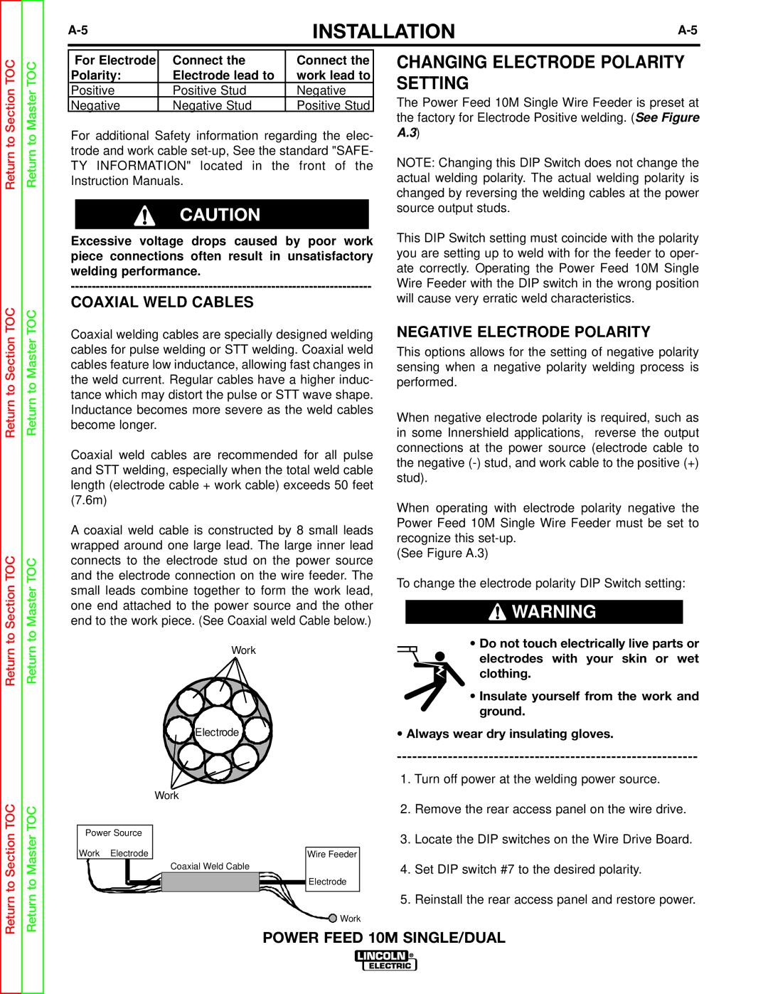
A coaxial weld cable is constructed by 8 small leads wrapped around one large lead. The large inner lead connects to the electrode stud on the power source and the electrode connection on the wire feeder. The small leads combine together to form the work lead, one end attached to the power source and the other end to the work piece. (See Coaxial weld Cable below.)
Work
![]() Electrode
Electrode ![]()
Work
CHANGING ELECTRODE POLARITY SETTING
The Power Feed 10M Single Wire Feeder is preset at the factory for Electrode Positive welding. (See Figure A.3)
NOTE: Changing this DIP Switch does not change the actual welding polarity. The actual welding polarity is changed by reversing the welding cables at the power source output studs.
This DIP Switch setting must coincide with the polarity you are setting up to weld with for the feeder to oper- ate correctly. Operating the Power Feed 10M Single Wire Feeder with the DIP switch in the wrong position will cause very erratic weld characteristics.
NEGATIVE ELECTRODE POLARITY
This options allows for the setting of negative polarity sensing when a negative polarity welding process is performed.
When negative electrode polarity is required, such as in some Innershield applications, reverse the output connections at the power source (electrode cable to the negative
When operating with electrode polarity negative the Power Feed 10M Single Wire Feeder must be set to recognize this
(See Figure A.3)
To change the electrode polarity DIP Switch setting:
![]() WARNING
WARNING
• Do not touch electrically live parts or electrodes with your skin or wet clothing.
•Insulate yourself from the work and ground.
•Always wear dry insulating gloves.
1.Turn off power at the welding power source.
Return to Section TOC
Return to Master TOC
|
|
| 2. | Remove the rear access panel on the wire drive. | ||
|
|
|
|
| ||
Power Source |
|
| 3. | Locate the DIP switches on the Wire Drive Board. | ||
|
|
| ||||
Work Electrode |
|
|
| Wire Feeder |
|
|
|
| Coaxial Weld Cable |
|
| 4. Set DIP switch #7 to the desired polarity. | |
|
|
|
| Electrode |
|
|
|
|
|
|
| ||
|
|
|
|
| ||
|
|
|
|
|
|
|
|
|
| 5. | Reinstall the rear access panel and restore power. | ||
![]() Work
Work
POWER FEED 10M SINGLE/DUAL