Return to Section TOC
Return to Section TOC
Return to Master TOC
Return to Master TOC
OPERATION | ||
|
|
|
MACHINE FUNCTIONALITY BY WELD PROCESS
CV GMAW/FCAW (NON-SYNERGIC)
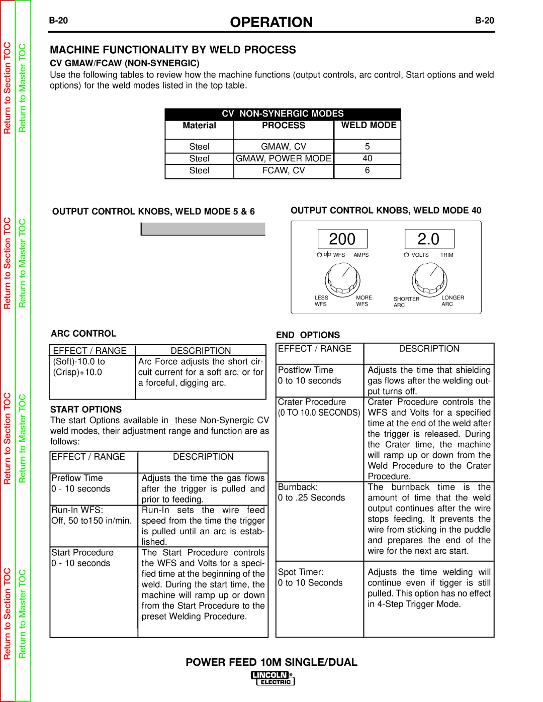
Use the following tables to review how the machine functions (output controls, arc control, Start options and weld options) for the weld modes listed in the top table.
CV NON-SYNERGIC MODES
Material | PROCESS | WELD MODE |
|
|
|
Steel | GMAW, CV | 5 |
|
|
|
Steel | GMAW, POWER MODE | 40 |
Steel | FCAW, CV | 6 |
|
|
|
OUTPUT CONTROL KNOBS, WELD MODE 5 & 6 OUTPUT CONTROL KNOBS, WELD MODE 40
300 | 25.3 | 200 | 2.0 |
WFS AMPS | VOLTS TRIM | WFS AMPS | VOLTS TRIM |
|
|
LESS | MORE | LESS | MORE | LESS | MORE | SHORTER | LONGER | |
WFS | WFS | WFS | WFS | ARC | ARC | |||
VOLTS | VOLTS | |||||||
|
|
|
|
|
|
Return to Section TOC
Return to Section TOC
Return to Master TOC
Return to Master TOC
ARC CONTROL
|
|
|
|
|
|
| EFFECT / RANGE |
|
| DESCRIPTION |
|
|
|
| Arc Force adjusts the short cir- |
| |
| (Crisp)+10.0 |
|
| cuit current for a soft arc, or for |
|
|
|
|
| a forceful, digging arc. |
|
|
|
|
|
|
|
|
|
|
|
|
|
|
|
|
|
|
|
START OPTIONS
The start Options available in these
|
|
|
|
|
EFFECT / RANGE |
|
| DESCRIPTION |
|
|
|
|
|
|
Preflow Time |
|
| Adjusts the time the gas flows |
|
0 - 10 seconds |
|
| after the trigger is pulled and |
|
|
|
| prior to feeding. |
|
|
|
| ||
Off, 50 to150 in/min. |
|
| speed from the time the trigger |
|
|
|
| is pulled until an arc is estab- |
|
|
|
| lished. |
|
Start Procedure |
|
| The Start Procedure controls |
|
0 - 10 seconds |
|
| the WFS and Volts for a speci- |
|
|
|
| fied time at the beginning of the |
|
|
|
| weld. During the start time, the |
|
|
|
| machine will ramp up or down |
|
|
|
| from the Start Procedure to the |
|
|
|
| preset Welding Procedure. |
|
|
|
|
|
|
|
|
|
|
|
|
|
|
|
|
|
|
|
|
|
END OPTIONS
|
|
|
|
|
EFFECT / RANGE |
|
| DESCRIPTION |
|
|
|
|
|
|
Postflow Time |
|
| Adjusts the time that shielding |
|
0 to 10 seconds |
|
| gas flows after the welding out- |
|
|
|
| put turns off. |
|
Crater Procedure |
|
| Crater Procedure controls the |
|
|
|
| ||
(0 TO 10.0 SECONDS) |
|
| WFS and Volts for a specified |
|
|
|
| time at the end of the weld after |
|
|
|
| the trigger is released. During |
|
|
|
| the Crater time, the machine |
|
|
|
| will ramp up or down from the |
|
|
|
| Weld Procedure to the Crater |
|
|
|
| Procedure. |
|
Burnback: |
|
| The burnback time is the |
|
0 to .25 Seconds |
|
| amount of time that the weld |
|
|
|
| output continues after the wire |
|
|
|
| stops feeding. It prevents the |
|
|
|
| wire from sticking in the puddle |
|
|
|
| and prepares the end of the |
|
|
|
| wire for the next arc start. |
|
|
|
|
|
|
Spot Timer: |
|
| Adjusts the time welding will |
|
0 to 10 Seconds |
|
| continue even if tigger is still |
|
|
|
| pulled. This option has no effect |
|
|
|
| in |
|
|
|
|
|
|
|
|
|
|
|
POWER FEED 10M SINGLE/DUAL
