Return to Section TOC
Return to Section TOC
Return to Section TOC
Return to Section TOC
Return to Master TOC
Return to Master TOC
Return to Master TOC
Return to Master TOC
| OPERATION |
|
|
|
|
|
|
|
| |||
|
|
|
|
|
|
|
|
|
|
|
| |
P.100 | View Diagnostics |
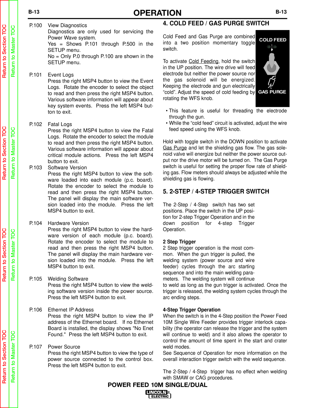
| 4. COLD FEED / GAS PURGE SWITCH |
| ||||||||
|
|
|
|
|
|
|
|
|
|
| ||
| Diagnostics are only used for servicing the | Cold Feed and Gas Purge are combined |
|
|
|
|
|
|
| |||
|
|
|
|
|
|
|
| |||||
| Power Wave system. |
| COLD FEED |
| ||||||||
| Yes = Shows P.101 through P.500 in the | into a two position momentary toggle |
| |||||||||
|
|
|
|
|
|
|
| |||||
| SETUP menu. |
| switch. |
|
|
|
|
|
|
|
|
|
| No = Only P.0 through P.100 are shown in the | To activate Cold Feeding, hold the switch |
|
|
|
|
|
|
| |||
| SETUP menu. |
|
|
|
|
|
|
|
| |||
|
|
| in the UP position. The wire drive will feed |
|
|
|
|
|
|
| ||
P.101 | Event Logs |
| electrode but neither the power source nor |
|
|
|
|
|
|
| ||
| Press the right MSP4 button to view the Event | the gas solenoid will be energized. |
|
|
|
|
|
|
| |||
| Logs. Rotate the encoder to select the object | Keeping the electrode and gun electrically |
|
|
|
|
|
|
| |||
| to read and then press the right MSP4 button. | “cold”. Adjust the speed of cold feeding by | GAS PURGE |
| ||||||||
| Various software information will appear about | rotating the WFS knob. |
|
|
|
|
|
|
| |||
| key system events. Press the left MSP4 but- |
|
|
|
|
|
|
|
|
|
| |
| • This feature is useful for threading the electrode |
| ||||||||||
| ton to exit. |
|
| |||||||||
|
|
| through the gun. |
|
|
|
|
|
|
|
|
|
P.102 | Fatal Logs |
| • While the “cold feed” circuit is activated, adjust the wire |
| ||||||||
| Press the right MSP4 button to view the Fatal | feed speed using the WFS knob. |
|
|
|
|
|
|
| |||
| Logs. Rotate the encoder to select the module | Hold with toggle switch in the DOWN position to activate |
| |||||||||
| to read and then press the right MSP4 button. |
| ||||||||||
| Various software information will appear about | Gas Purge and let the shielding gas flow. The gas sole- |
| |||||||||
| critical module actions. Press the left MSP4 | noid valve will energize but neither the power source out- |
| |||||||||
| button to exit. |
| put nor the drive motor will be turned on. The Gas Purge |
| ||||||||
P.103 | Software Version |
| switch is useful for setting the proper flow rate of shield- |
| ||||||||
| Press the right MSP4 button to view the soft- | ing gas. Flow meters should always be adjusted while the |
| |||||||||
| ware loaded into each module (p.c. board). | shielding gas is flowing. |
|
|
|
|
|
|
| |||
| Rotate the encoder to select the module to | 5. |
| |||||||||
| read and then press the right MSP4 button. |
| ||||||||||
| The panel will display the main software ver- |
|
|
|
|
|
|
|
|
|
| |
| sion loaded into the module. | Press the left | The | switch has two set |
| 2 |
|
| ||||
| MSP4 button to exit. |
| positions. Place the switch in the UP posi- |
|
| |||||||
|
|
| tion for |
|
|
|
|
|
|
|
| |
|
|
|
|
|
|
|
|
|
|
| ||
P.104 | Hardware Version |
| down position for |
|
|
|
|
|
|
|
| |
| Press the right MSP4 button to view the hard- | Operation. |
|
|
|
|
|
|
|
|
| |
| ware version of each module (p.c. board). |
|
|
|
|
|
|
|
|
|
| |
| Rotate the encoder to select the module to | 2 Step Trigger |
|
|
|
|
|
|
|
|
| |
| read and then press the right MSP4 button. | 2 Step trigger operation is the most com- |
|
|
|
|
|
|
|
| ||
|
|
|
|
|
|
|
|
| ||||
| The panel will display the main hardware ver- | mon. When the gun trigger is pulled, the |
|
|
|
|
|
|
|
| ||
|
|
|
|
|
|
|
|
| ||||
| sion loaded into the module. | Press the left | welding system (power source and wire |
| 4 STEP |
| ||||||
| MSP4 button to exit. |
| feeder) cycles through the arc starting |
|
| |||||||
|
|
| sequence and into the main welding para- |
|
|
|
|
|
|
|
| |
P.105 | Welding Software |
| meters. The welding system will continue |
|
|
|
|
|
|
|
| |
|
|
|
|
|
|
|
|
| ||||
| Press the right MSP4 button to view the weld- | to weld as long as the gun trigger is activated. Once the |
| |||||||||
| ing software version inside the power source. | trigger is released, the welding system cycles through the |
| |||||||||
| Press the left MSP4 button to exit. | arc ending steps. |
|
|
|
|
|
|
|
|
| |
P.106 | Ethernet IP Address |
|
|
|
|
|
|
|
|
| ||
| Press the right MSP4 button to view the IP | When the switch is in the |
| |||||||||
| address of the Ethernet board. | If no Ethernet | 10M Single Wire Feeder provides trigger interlock capa- |
| ||||||||
| Board is installed, the display shows "No Enet | bility (the operator can release the trigger and the system |
| |||||||||
| Found." Press the left MSP4 button to exit. | will continue to weld) and it also allows the operator to |
| |||||||||
|
|
| control the amount of time spent in the start and crater |
| ||||||||
P.107 | Power Source |
| weld modes. |
|
|
|
|
|
|
|
|
|
| Press the right MSP4 button to view the type of | See Sequence of Operation for more information on the |
| |||||||||
| power source connected to the control box. | overall interaction trigger switch with the weld sequence. |
| |||||||||
| Press the left MSP4 button to exit. |
|
|
|
|
|
|
|
|
|
| |
|
|
| The | trigger has no effect when welding |
| |||||||
|
|
| with SMAW or CAG procedures. |
|
|
|
|
|
|
| ||
POWER FEED 10M SINGLE/DUAL