| OPERATION | |
|
|
|
Return to Section TOC
Return to Section TOC
Return to Section TOC
Return to Section TOC
Return to Master TOC
Return to Master TOC
Return to Master TOC
Return to Master TOC
LIMIT SETTING
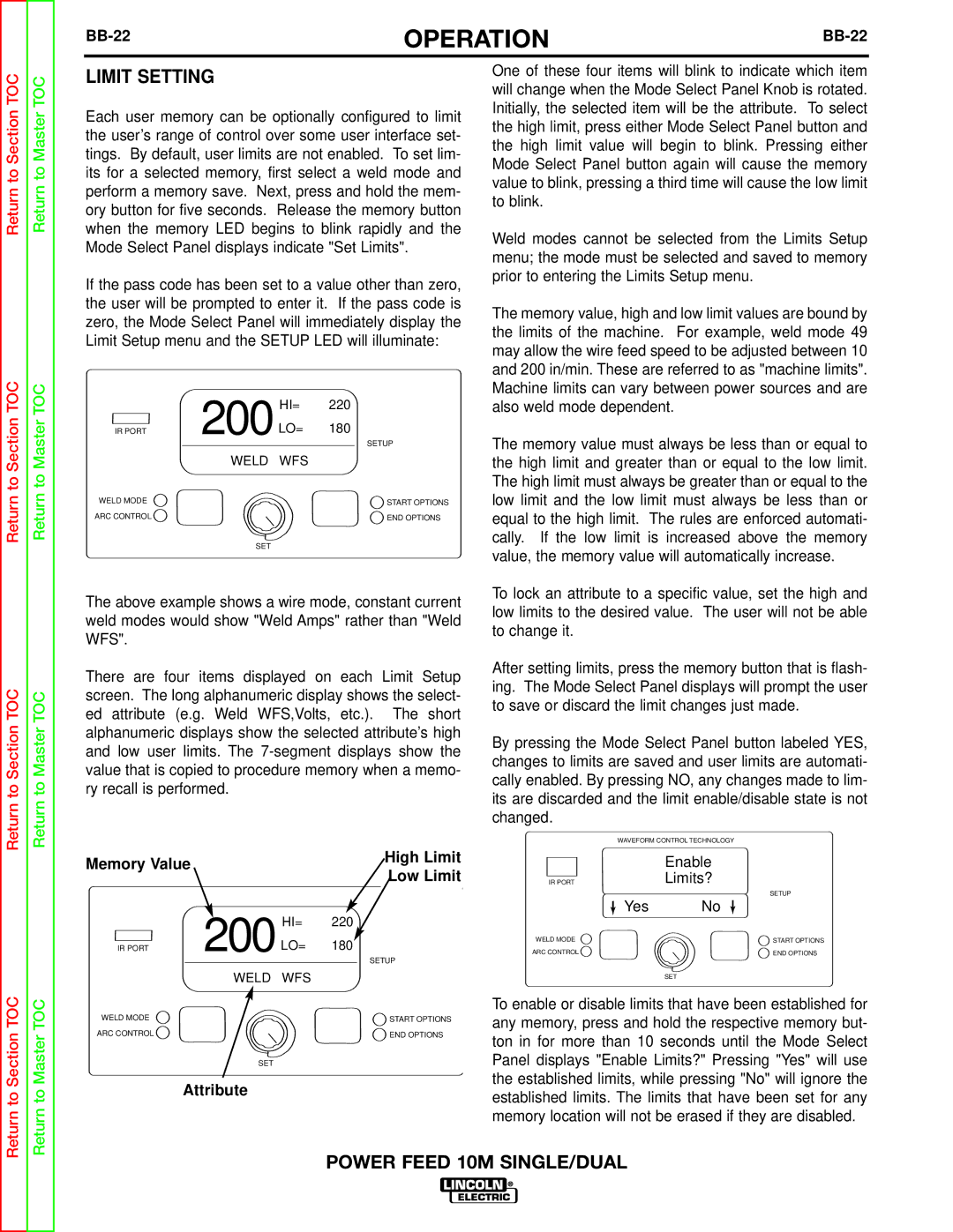
Each user memory can be optionally configured to limit the user’s range of control over some user interface set- tings. By default, user limits are not enabled. To set lim- its for a selected memory, first select a weld mode and perform a memory save. Next, press and hold the mem- ory button for five seconds. Release the memory button when the memory LED begins to blink rapidly and the Mode Select Panel displays indicate "Set Limits".
If the pass code has been set to a value other than zero, the user will be prompted to enter it. If the pass code is zero, the Mode Select Panel will immediately display the Limit Setup menu and the SETUP LED will illuminate:
| 200 | HI= | 220 |
IR PORT | LO= | 180 | |
|
|
| SETUP |
| WELD | WFS |
|
WELD MODE |
|
| START OPTIONS |
ARC CONTROL |
|
| END OPTIONS |
| SET |
|
|
The above example shows a wire mode, constant current weld modes would show "Weld Amps" rather than "Weld WFS".
There are four items displayed on each Limit Setup screen. The long alphanumeric display shows the select- ed attribute (e.g. Weld WFS,Volts, etc.). The short alphanumeric displays show the selected attribute’s high and low user limits. The
Memory Value |
|
| High Limit | |
|
| Low Limit | ||
|
|
| ||
| 200 | HI= | 220 | |
IR PORT | LO= | 180 | ||
| ||||
|
|
| SETUP | |
| WELD | WFS |
| |
WELD MODE |
|
| START OPTIONS | |
ARC CONTROL |
|
| END OPTIONS |
SET
Attribute
One of these four items will blink to indicate which item will change when the Mode Select Panel Knob is rotated. Initially, the selected item will be the attribute. To select the high limit, press either Mode Select Panel button and the high limit value will begin to blink. Pressing either Mode Select Panel button again will cause the memory value to blink, pressing a third time will cause the low limit to blink.
Weld modes cannot be selected from the Limits Setup menu; the mode must be selected and saved to memory prior to entering the Limits Setup menu.
The memory value, high and low limit values are bound by the limits of the machine. For example, weld mode 49 may allow the wire feed speed to be adjusted between 10 and 200 in/min. These are referred to as "machine limits". Machine limits can vary between power sources and are also weld mode dependent.
The memory value must always be less than or equal to the high limit and greater than or equal to the low limit. The high limit must always be greater than or equal to the low limit and the low limit must always be less than or equal to the high limit. The rules are enforced automati- cally. If the low limit is increased above the memory value, the memory value will automatically increase.
To lock an attribute to a specific value, set the high and low limits to the desired value. The user will not be able to change it.
After setting limits, press the memory button that is flash- ing. The Mode Select Panel displays will prompt the user to save or discard the limit changes just made.
By pressing the Mode Select Panel button labeled YES, changes to limits are saved and user limits are automati- cally enabled. By pressing NO, any changes made to lim- its are discarded and the limit enable/disable state is not changed.
WAVEFORM CONTROL TECHNOLOGY
| Enable |
IR PORT | Limits? |
| SETUP |
Yes | No |
WELD MODE | START OPTIONS |
ARC CONTROL | END OPTIONS |
| SET |
To enable or disable limits that have been established for any memory, press and hold the respective memory but- ton in for more than 10 seconds until the Mode Select Panel displays "Enable Limits?" Pressing "Yes" will use the established limits, while pressing "No" will ignore the established limits. The limits that have been set for any memory location will not be erased if they are disabled.
