|
|
| Levels of Implementation | |
|
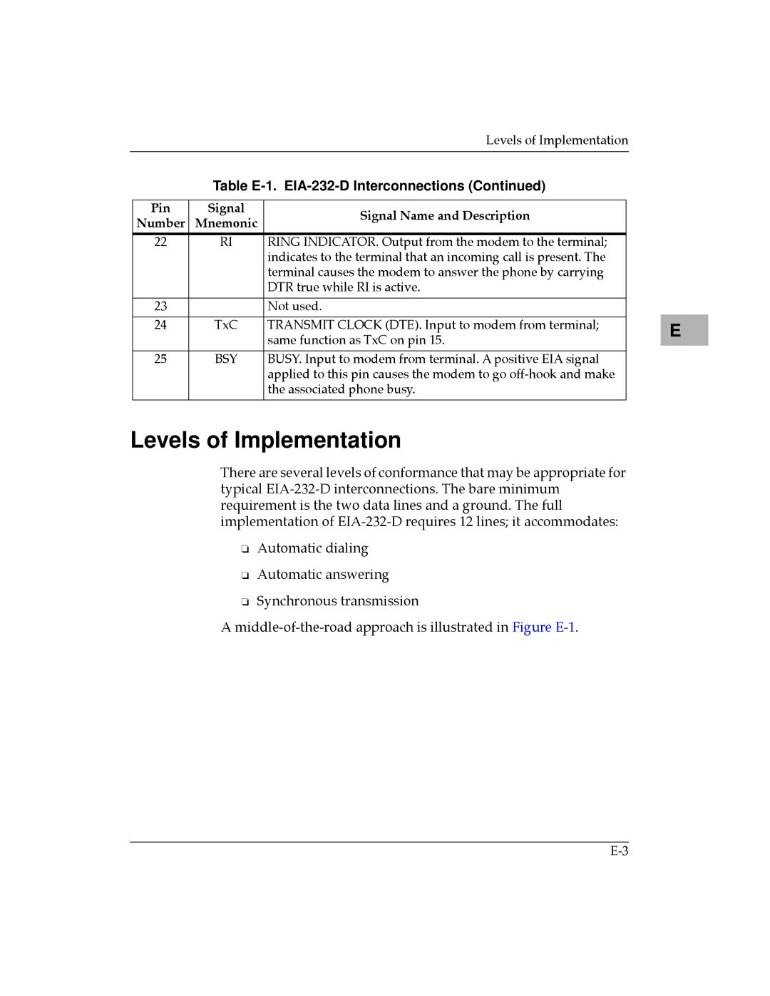
| Table | ||
|
|
|
|
|
| Pin | Signal | Signal Name and Description |
|
| Number | Mnemonic |
| |
|
|
| ||
|
|
|
|
|
| 22 | RI | RING INDICATOR. Output from the modem to the terminal; |
|
|
|
| indicates to the terminal that an incoming call is present. The |
|
|
|
| terminal causes the modem to answer the phone by carrying |
|
|
|
| DTR true while RI is active. |
|
|
|
|
|
|
| 23 |
| Not used. |
|
|
|
|
|
|
| 24 | TxC | TRANSMIT CLOCK (DTE). Input to modem from terminal; |
|
|
|
| same function as TxC on pin 15. |
|
|
|
|
|
|
| 25 | BSY | BUSY. Input to modem from terminal. A positive EIA signal |
|
|
|
| applied to this pin causes the modem to go |
|
|
|
| the associated phone busy. |
|
|
|
|
|
|
Levels of Implementation
There are several levels of conformance that may be appropriate for typical
❏Automatic dialing
❏Automatic answering
❏Synchronous transmission
A
E |