|
|
| Installing the Hardware | |
|
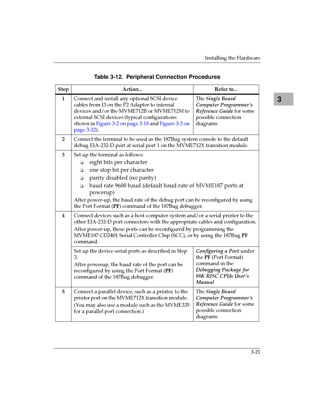
| Table | ||
|
|
|
|
|
| Step | Action... | Refer to... |
|
|
|
|
|
|
| 1 | Connect and install any optional SCSI device | The Single Board |
|
|
| cables from J3 on the P2 Adapter to internal | Computer Programmer's |
|
|
| devices and/or the MVME712B or MVME712M to | Reference Guide for some |
|
|
| external SCSI devices (typical conÞgurations | possible connection |
|
|
| shown in Figure | diagrams |
|
|
| page |
|
|
|
|
|
|
|
| 2 | Connect the terminal to be used as the 187Bug system console to the default |
| |
|
| debug |
| |
|
|
|
|
|
| 3 | Set up the terminal as follows: |
|
|
|
| ❏ eight bits per character |
|
|
|
| ❏ one stop bit per character |
|
|
|
| ❏ parity disabled (no parity) |
|
|
|
| ❏ baud rate 9600 baud (default baud rate of MVME187 ports at |
| |
|
| powerup) |
|
|
|
| After |
| |
|
| the Port Format (PF) command of the 187Bug debugger. |
| |
|
|
|
| |
| 4 | Connect devices such as a host computer system and/or a serial printer to the |
| |
|
| other |
| |
|
| After |
| |
|
| MVME187 CD2401 Serial Controller Chip (SCC), or by using the 187Bug PF |
| |
|
| command. |
|
|
|
|
|
|
|
|
| Set up the device serial ports as described in Step | ConÞguring a Port under |
|
|
| 3. | the PF (Port Format) |
|
|
| After powerup, the baud rate of the port can be | command in the |
|
|
| reconÞgured by using the Port Format (PF) | Debugging Package for |
|
|
| command of the 187Bug debugger. | 88K RISC CPUs UserÕs |
|
|
|
| Manual |
|
|
|
|
|
|
| 5 | Connect a parallel device, such as a printer, to the | The Single Board |
|
|
| printer port on the MVME712X transition module. | Computer Programmer's |
|
|
| (You may also use a module such as the MVME335 | Reference Guide for some |
|
|
| for a parallel port connection.) | possible connection |
|
|
|
| diagrams |
|
|
|
|
|
|
3 |