Motorola MVME187 manual I N D E, see also CD2401 scientific notation 5-14 SCON LED

Models: MVME187

1 173
Download 173 pages 29 Kb
Page 171
Image 171
see also CD2401 scientific notation 5-14 SCON LED 2-11

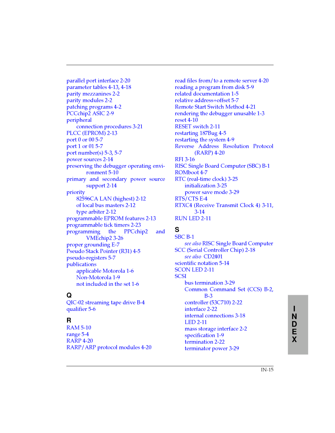
parallel port interface 2-20 parameter tables 4-13,4-18parity mezzanines 2-2parity modules 2-2patching programs 4-2PCCchip2 ASIC 2-9peripheral

connection procedures 3-21PLCC (EPROM) 2-13

port 0 or 00 5-7port 1 or 01 5-7

port number(s) 5-3, 5-7 power sources 2-14

preserving the debugger operating envi- ronment 5-10

primary and secondary power source support 2-14

priority

82596CA LAN (highest) 2-12of local bus masters 2-12type arbiter 2-12

programmable EPROM features 2-13programmable tick timers 2-23 programming the PPCchip2 and

VMEchip2 3-26

proper grounding E-7

Pseudo Stack Pointer (R31) 4-5 pseudo-registers 5-7 publications

applicable Motorola 1-6Non-Motorola 1-9

not included in the set 1-6

Q

QIC-02 streaming tape drive B-4qualifier 5-6

R

RAM 5-10 range 5-4 RARP 4-20

RARP/ARP protocol modules 4-20

read files from/to a remote server 4-20 reading a program from disk 5-9 related documentation 1-5

relative address+offset 5-7 Remote Start Switch Method 4-21 rendering the debugger unusable 1-3 reset 4-10

RESET switch 2-11 restarting 187Bug 4-5 restarting the system 4-9

Reverse Address Resolution Protocol (RARP) 4-20

RFI 3-16

RISC Single Board Computer (SBC) B-1 ROMboot 4-7

RTC (real-time clock) 3-25initialization 3-25 power save mode 3-29

RTS/CTS E-4

RTXC4 (Receive Transmit Clock 4) 3-11, 3-14

RUN LED 2-11

S

SBC B-1

see also RISC Single Board Computer SCC (Serial Controller Chip) 2-18

see also CD2401 scientific notation 5-14 SCON LED 2-11

SCSI

bus termination 3-29

Common Command Set (CCS) B-2,B-3

controller (53C710) 2-22interface 2-22

internal connections 3-18 LED 2-11

mass storage interface 2-2 specification 1-9 termination 2-22 terminator power 3-29

I

N D E X

IN-15

Page 171
Image 171
Motorola MVME187 manual I N D E, see also CD2401 scientific notation 5-14 SCON LED