Preparing the Hardware
Preparing the System Chassis
Now that the MVME187 module is ready for installation, prepare the system chassis and determine slot assignments (for peripherals, transition modules, etc.) as follows:
Inserting or removing modules while power is applied
! could result in damage to module components.
Caution
Dangerous voltages, capable of causing death, are
! present in this equipment. Use extreme caution when
Warning handling, testing, and adjusting.
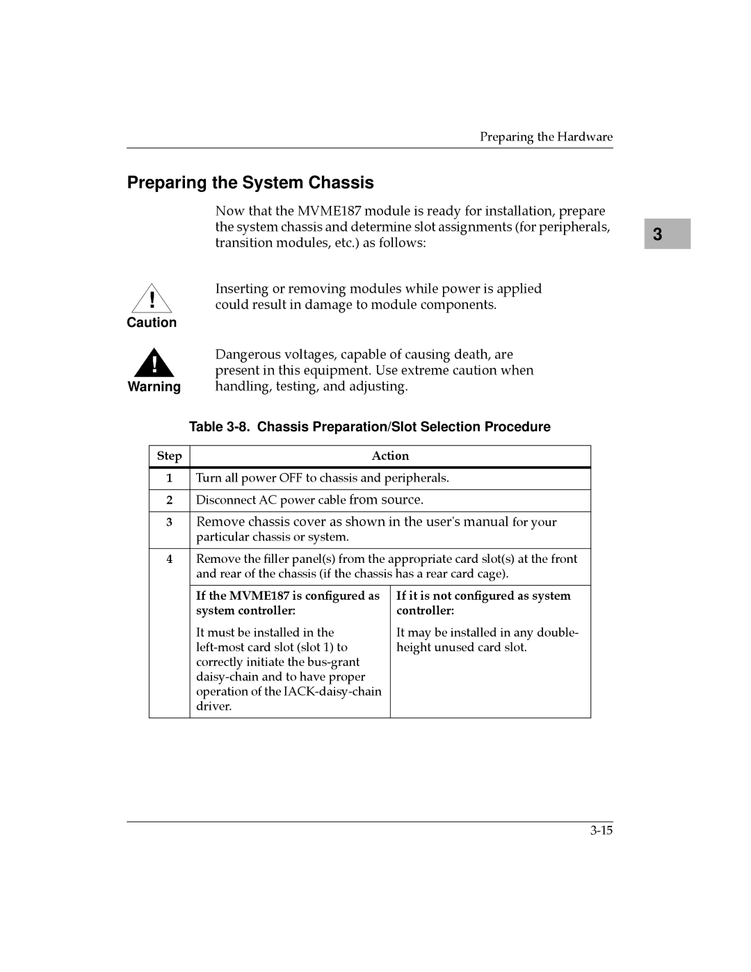
Table 3-8. Chassis Preparation/Slot Selection Procedure
Step | Action | |
|
| |
1 | Turn all power OFF to chassis and peripherals. | |
|
| |
2 | Disconnect AC power cable from source. | |
|
| |
3 | Remove chassis cover as shown in the user's manual for your | |
| particular chassis or system. |
|
|
| |
4 | Remove the Þller panel(s) from the appropriate card slot(s) at the front | |
| and rear of the chassis (if the chassis has a rear card cage). | |
|
|
|
| If the MVME187 is conÞgured as | If it is not conÞgured as system |
| system controller: | controller: |
| It must be installed in the | It may be installed in any double- |
| height unused card slot. | |
| correctly initiate the |
|
|
| |
| operation of the |
|
| driver. |
|
|
|
|
3 |
