E |
|
| Table | ||
|
|
|
| |
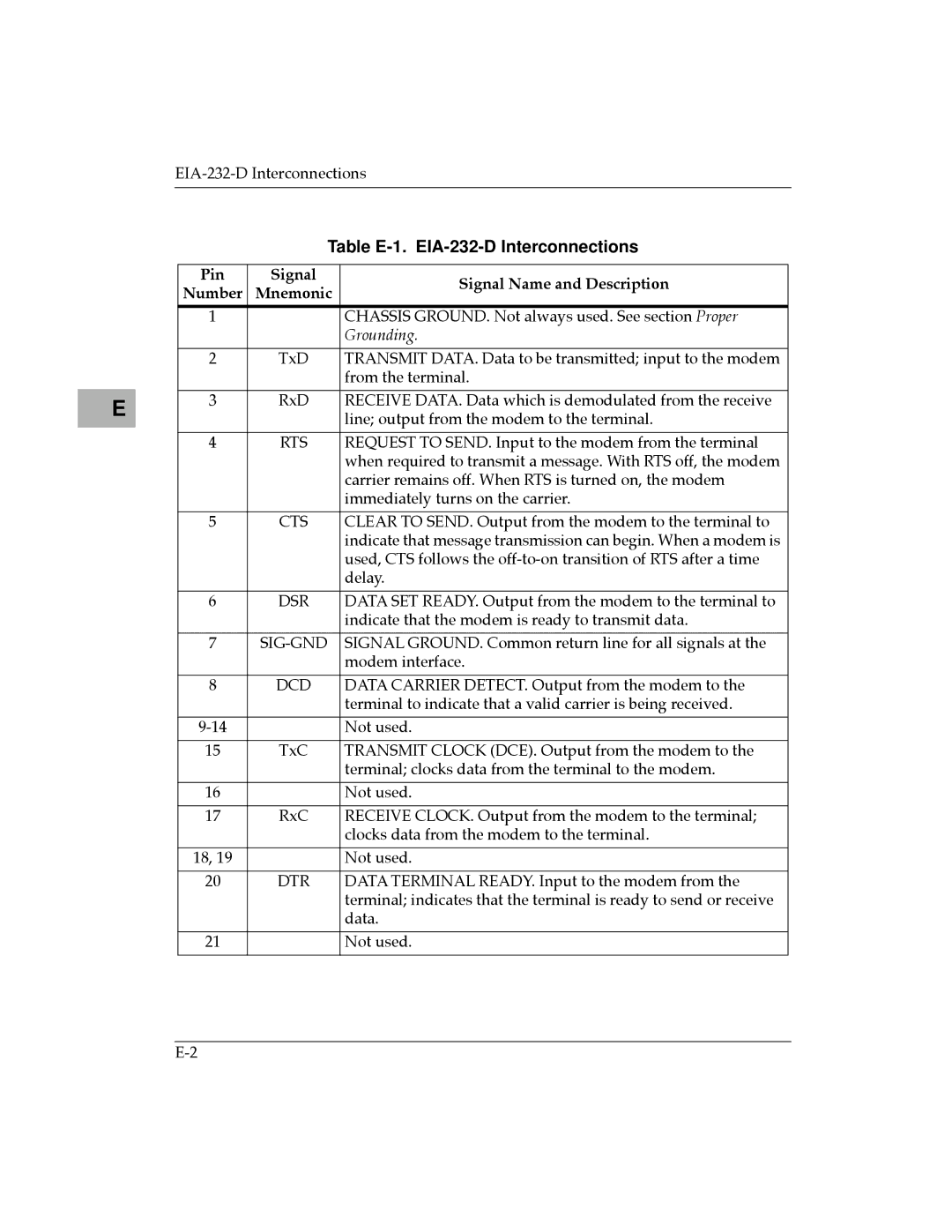
Pin | Signal |
| Signal Name and Description | |
Number | Mnemonic | |||
| ||||
|
|
|
| |
1 |
|
| CHASSIS GROUND. Not always used. See section Proper | |
|
|
| Grounding. | |
|
|
|
| |
2 | TxD |
| TRANSMIT DATA. Data to be transmitted; input to the modem | |
|
|
| from the terminal. | |
|
|
|
| |
3 | RxD |
| RECEIVE DATA. Data which is demodulated from the receive | |
|
|
| line; output from the modem to the terminal. | |
|
|
|
| |
4 | RTS |
| REQUEST TO SEND. Input to the modem from the terminal | |
|
|
| when required to transmit a message. With RTS off, the modem | |
|
|
| carrier remains off. When RTS is turned on, the modem | |
|
|
| immediately turns on the carrier. | |
|
|
|
| |
5 | CTS |
| CLEAR TO SEND. Output from the modem to the terminal to | |
|
|
| indicate that message transmission can begin. When a modem is | |
|
|
| used, CTS follows the | |
|
|
| delay. | |
|
|
|
| |
6 | DSR |
| DATA SET READY. Output from the modem to the terminal to | |
|
|
| indicate that the modem is ready to transmit data. | |
|
|
|
| |
7 |
| SIGNAL GROUND. Common return line for all signals at the | ||
|
|
| modem interface. | |
|
|
|
| |
8 | DCD |
| DATA CARRIER DETECT. Output from the modem to the | |
|
|
| terminal to indicate that a valid carrier is being received. | |
|
|
|
| |
|
| Not used. | ||
|
|
|
| |
15 | TxC |
| TRANSMIT CLOCK (DCE). Output from the modem to the | |
|
|
| terminal; clocks data from the terminal to the modem. | |
|
|
|
| |
16 |
|
| Not used. | |
|
|
|
| |
17 | RxC |
| RECEIVE CLOCK. Output from the modem to the terminal; | |
|
|
| clocks data from the modem to the terminal. | |
|
|
|
| |
18, 19 |
|
| Not used. | |
|
|
|
| |
20 | DTR |
| DATA TERMINAL READY. Input to the modem from the | |
|
|
| terminal; indicates that the terminal is ready to send or receive | |
|
|
| data. | |
|
|
|
| |
21 |
|
| Not used. | |
|
|
|
| |