Memory Maps
Table 2-6. Local I/O Devices Memory Map (Continued)
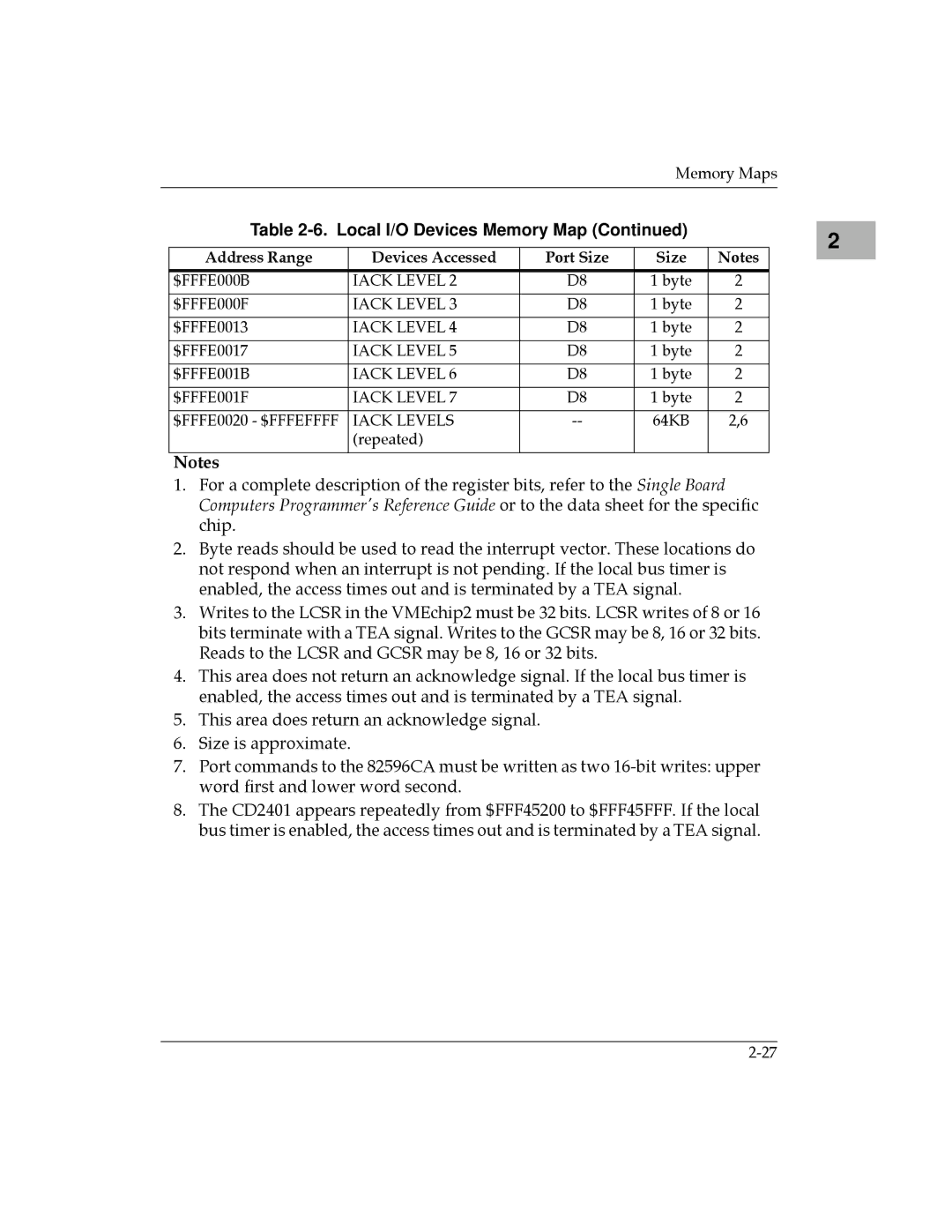
Address Range | Devices Accessed | Port Size | Size | Notes |
|
|
|
|
|
$FFFE000B | IACK LEVEL 2 | D8 | 1 byte | 2 |
|
|
|
|
|
$FFFE000F | IACK LEVEL 3 | D8 | 1 byte | 2 |
|
|
|
|
|
$FFFE0013 | IACK LEVEL 4 | D8 | 1 byte | 2 |
|
|
|
|
|
$FFFE0017 | IACK LEVEL 5 | D8 | 1 byte | 2 |
|
|
|
|
|
$FFFE001B | IACK LEVEL 6 | D8 | 1 byte | 2 |
|
|
|
|
|
$FFFE001F | IACK LEVEL 7 | D8 | 1 byte | 2 |
|
|
|
|
|
$FFFE0020 - $FFFEFFFF | IACK LEVELS | 64KB | 2,6 | |
| (repeated) |
|
|
|
|
|
|
|
|
Notes
1.For a complete description of the register bits, refer to the Single Board Computers Programmer's Reference Guide or to the data sheet for the specific chip.
2.Byte reads should be used to read the interrupt vector. These locations do not respond when an interrupt is not pending. If the local bus timer is enabled, the access times out and is terminated by a TEA signal.
3.Writes to the LCSR in the VMEchip2 must be 32 bits. LCSR writes of 8 or 16 bits terminate with a TEA signal. Writes to the GCSR may be 8, 16 or 32 bits. Reads to the LCSR and GCSR may be 8, 16 or 32 bits.
4.This area does not return an acknowledge signal. If the local bus timer is enabled, the access times out and is terminated by a TEA signal.
5.This area does return an acknowledge signal.
6.Size is approximate.
7.Port commands to the 82596CA must be written as two
8.The CD2401 appears repeatedly from $FFF45200 to $FFF45FFF. If the local bus timer is enabled, the access times out and is terminated by a TEA signal.
2 |