Motorola TMS320C6711D warranty Power-supply decoupling, Power-supply design considerations, Dvdd

Models: TMS320C6711D

1 107
Download 107 pages 8.75 Kb
Page 57
Image 57

SPRS292A − OCTOBER 2005 − REVISED NOVEMBER 2005

power-supply design considerations
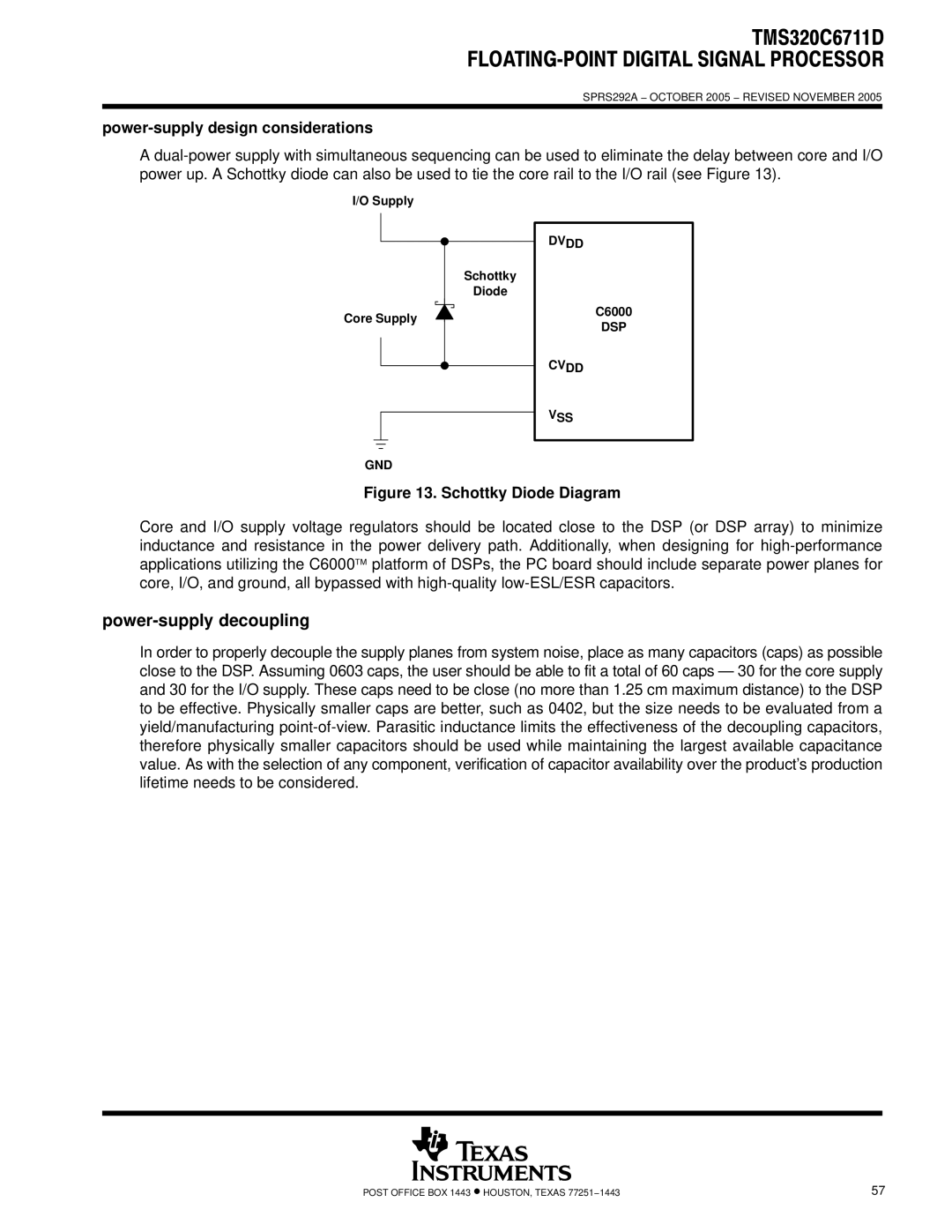
A dual-power supply with simultaneous sequencing can be used to eliminate the delay between core and I/O power up. A Schottky diode can also be used to tie the core rail to the I/O rail (see Figure 13).

I/O Supply

Schottky

Diode

Core Supply

DVDD

C6000

DSP

CVDD

VSS

GND

Figure 13. Schottky Diode Diagram

Core and I/O supply voltage regulators should be located close to the DSP (or DSP array) to minimize inductance and resistance in the power delivery path. Additionally, when designing for high-performance applications utilizing the C6000platform of DSPs, the PC board should include separate power planes for core, I/O, and ground, all bypassed with high-quality low-ESL/ESR capacitors.

power-supply decoupling

In order to properly decouple the supply planes from system noise, place as many capacitors (caps) as possible close to the DSP. Assuming 0603 caps, the user should be able to fit a total of 60 caps — 30 for the core supply and 30 for the I/O supply. These caps need to be close (no more than 1.25 cm maximum distance) to the DSP to be effective. Physically smaller caps are better, such as 0402, but the size needs to be evaluated from a yield/manufacturing point-of-view. Parasitic inductance limits the effectiveness of the decoupling capacitors, therefore physically smaller capacitors should be used while maintaining the largest available capacitance value. As with the selection of any component, verification of capacitor availability over the product’s production lifetime needs to be considered.

POST OFFICE BOX 1443 HOUSTON, TEXAS 77251−1443

57

Page 57
Image 57
Motorola TMS320C6711D warranty Power-supply decoupling, Power-supply design considerations, Dvdd, DSP Cvdd VSS GND