|
|
|
|
|
|
|
|
| SPRS292A − OCTOBER 2005 − REVISED NOVEMBER 2005 |
| ||||
|
|
|
|
|
|
|
|
|
|
|
|
|
| |
|
|
|
|
|
| Terminal Functions (Continued) |
| |||||||
|
|
|
|
|
|
|
|
|
|
|
|
|
|
|
|
|
| PIN |
|
|
|
|
|
|
|
|
|
|
|
| SIGNAL | NO. | TYPE† | IPD/ |
|
|
| DESCRIPTION |
| |||||
|
|
|
|
|
| |||||||||
| NAME | GDP/ | IPU‡ |
|
|
|
| |||||||
|
|
|
|
|
|
|
|
|
|
| ||||
|
|
| ZDP |
|
|
|
|
|
|
|
|
|
|
|
|
|
|
|
|
|
|
|
|
|
|
|
|
| |
|
|
|
|
|
| JTAG EMULATION (CONTINUED) |
| |||||||
|
|
|
|
|
|
|
|
|
|
|
|
|
| |
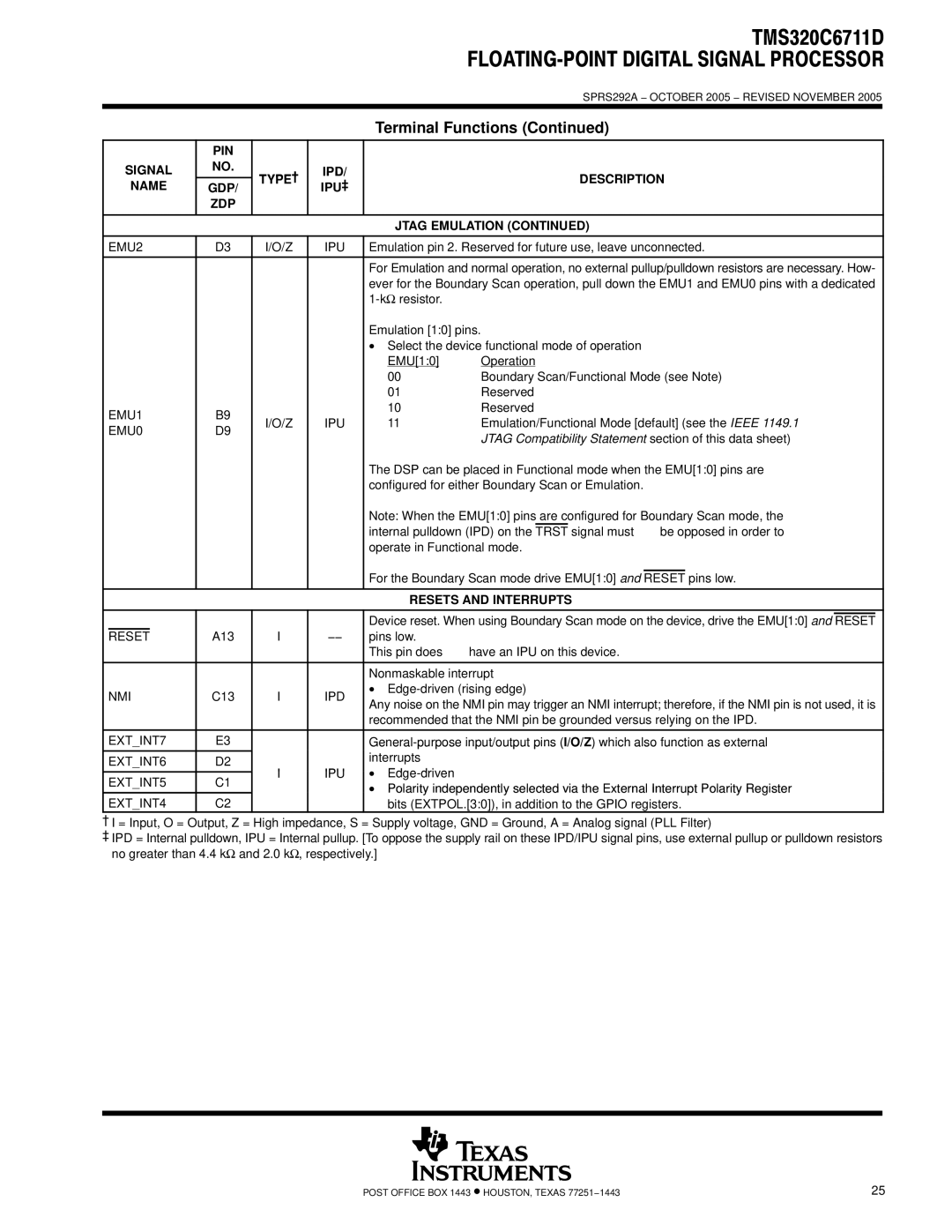
| EMU2 | D3 | I/O/Z | IPU | Emulation pin 2. Reserved for future use, leave unconnected. |
| ||||||||
|
|
|
|
|
|
|
|
|
| |||||
|
|
|
|
|
| For Emulation and normal operation, no external pullup/pulldown resistors are necessary. How- |
| |||||||
|
|
|
|
|
| ever for the Boundary Scan operation, pull down the EMU1 and EMU0 pins with a dedicated |
| |||||||
|
|
|
|
|
|
|
|
|
|
|
|
|
| |
|
|
|
|
|
| Emulation [1:0] pins. |
|
|
|
|
|
|
|
|
|
|
|
|
|
| • Select the device functional mode of operation |
| |||||||
|
|
|
|
|
| EMU[1:0] | Operation |
| ||||||
|
|
|
|
|
| 00 | Boundary Scan/Functional Mode (see Note) |
| ||||||
|
|
|
|
|
| 01 | Reserved |
| ||||||
| EMU1 | B9 |
|
| 10 | Reserved |
| |||||||
| I/O/Z | IPU | 11 | Emulation/Functional Mode [default] (see the IEEE 1149.1 |
| |||||||||
| EMU0 | D9 |
| |||||||||||
|
|
|
| JTAG Compatibility Statement section of this data sheet) |
| |||||||||
|
|
|
|
|
|
|
| |||||||
|
|
|
|
|
| The DSP can be placed in Functional mode when the EMU[1:0] pins are |
| |||||||
|
|
|
|
|
| configured for either Boundary Scan or Emulation. |
| |||||||
|
|
|
|
|
| Note: When the EMU[1:0] pins are configured for Boundary Scan mode, the |
| |||||||
|
|
|
|
|
| internal pulldown (IPD) on the | TRST | signal must not be opposed in order to |
| |||||
|
|
|
|
|
| operate in Functional mode. |
| |||||||
|
|
|
|
|
|
|
|
|
| |||||
|
|
|
|
|
| For the Boundary Scan mode drive EMU[1:0] and | RESET | pins low. |
| |||||
|
|
|
|
|
|
|
|
|
|
|
|
|
| |
|
|
|
|
|
| RESETS AND INTERRUPTS |
| |||||||
|
|
|
|
|
|
|
|
| ||||||
|
|
|
|
|
| Device reset. When using Boundary Scan mode on the device, drive the EMU[1:0] and | RESET |
|
| |||||
| RESET |
| A13 | I | −− | pins low. |
|
|
|
|
|
|
|
|
|
|
|
|
|
| This pin does not have an IPU on this device. |
| |||||||
|
|
|
|
|
|
|
|
| ||||||
|
|
|
|
|
| Nonmaskable interrupt |
| |||||||
| NMI | C13 | I | IPD | • |
| ||||||||
| Any noise on the NMI pin may trigger an NMI interrupt; therefore, if the NMI pin is not used, it is |
| ||||||||||||
|
|
|
|
|
|
| ||||||||
|
|
|
|
|
| recommended that the NMI pin be grounded versus relying on the IPD. |
| |||||||
|
|
|
|
|
|
|
| |||||||
| EXT_INT7 | E3 |
|
|
| |||||||||
| EXT_INT6 | D2 |
|
| interrupts |
|
|
|
|
|
|
|
| |
| I | IPU | • |
|
|
|
|
|
|
|
| |||
|
|
|
|
|
|
|
|
|
|
|
| |||
| EXT_INT5 | C1 |
|
|
|
|
|
|
|
| ||||
|
|
| • Polarity independently selected via the External Interrupt Polarity Register |
| ||||||||||
|
|
|
|
|
|
| ||||||||
| EXT_INT4 | C2 |
|
| bits (EXTPOL.[3:0]), in addition to the GPIO registers. |
| ||||||||
†I = Input, O = Output, Z = High impedance, S = Supply voltage, GND = Ground, A = Analog signal (PLL Filter)
‡IPD = Internal pulldown, IPU = Internal pullup. [To oppose the supply rail on these IPD/IPU signal pins, use external pullup or pulldown resistors no greater than 4.4 kΩ and 2.0 kΩ, respectively.]
POST OFFICE BOX 1443 • HOUSTON, TEXAS 77251−1443 | 25 |
