EX- FCCS
Data Programming
STEP 2: ARTD
Assign the following three routes for this feature:
•Speech Path Route (Traffic Route)
•Signaling Route
•Dummy Route (Flag Route)
Assign each route data in accordance with the table shown below. Note that data assignment in this table is a typical example.
Route |
|
|
|
|
|
| CDN |
|
|
|
|
|
| |
|
|
|
|
|
|
|
|
|
|
|
|
| ||
2 | 4 | 5 | 6 | 7 | 8 | 13 | 15 | 28 | 30 | 43 | 49 | 50 | ||
| ||||||||||||||
|
|
|
|
|
|
|
|
|
|
|
|
|
| |
Speech | 2 | 2 | 3 | 4 | 1 | 2 | 0 | 12 | 1 | 0 | 1 | 0/1 | 1 | |
|
|
|
|
|
|
|
|
|
|
|
|
|
| |
Signaling | 2 | 2 | 0 | 4 | 1 | 0 | 0 | 13 | 0 | 7 | 0 | 0 | 0 | |
|
|
|
|
|
|
|
|
|
|
|
|
|
| |
Dummy | 0 | 0 | 0 | 4 | 1 | 0 | 1 | 0 | 0 | 0 | 0 | 0 | 0 | |
|
|
|
|
|
|
|
|
|
|
|
|
|
|
The other data than above should be set “0” (default data).
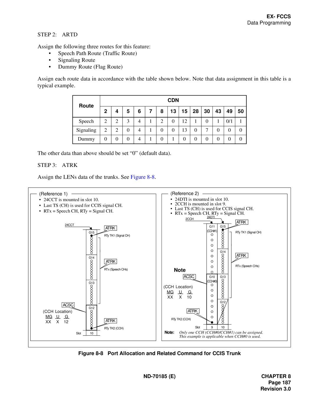
STEP 3: ATRK
Assign the LENs data of the trunks. See Figure 8-8.
(Reference 1)
•24CCT is mounted in slot 10.
•Last TS (CH) is used for CCIS signal CH.
•RTx = Speech CH, RTy = Signal CH.
(Reference 2)
•24DTI is mounted in slot 10.
•2CCH is mounted in slot 9.
•Last TS (CH) is used for CCIS signal CH.
•RTx = Speech CH, RTy = Signal CH.
2CCH
24DTI |
ATRK
24CCT
ACSC
(CCH Location)
MG U G XX X 12
G15 |
G14 |
G13 |
G12 |
ATRK
RTy TK1 (Signal CH)
ATRK
RTx (Speech CHs)
ATRK
RTy TK2 (CCH)
Note
ACSC
(CCH Location)
MG U G XX X 10
ATRK
RTy TK2 (CCH)
Slot
| G11 | G15 |
|
|
| (CCH#1) |
|
|
|
|
|
|
|
|
|
| G14 |
|
|
|
|
|
|
|
| G10 | G13 |
|
|
| (CCH#0) |
|
|
|
|
|
|
|
|
|
|
|
|
|
|
| G12 |
|
|
|
|
|
|
|
| 9 | 10 |
|
|
RTy TK1 (Signal CH)
ATRK
RTx (Speech CHs)
Slot
10 |
Note: Only one CCH (CCH#0/CCH#1) can be assigned. This example is applicable when CCH#0 is used.
Figure 8-8 Port Allocation and Related Command for CCIS Trunk
ND-70185 (E)CHAPTER 8
Page 187