TROUBLESHOOTING
13-H/I/J Signaling Link Failure (Permanent)/(Temporary)/(Recovery)
6.1Repair Procedure
•
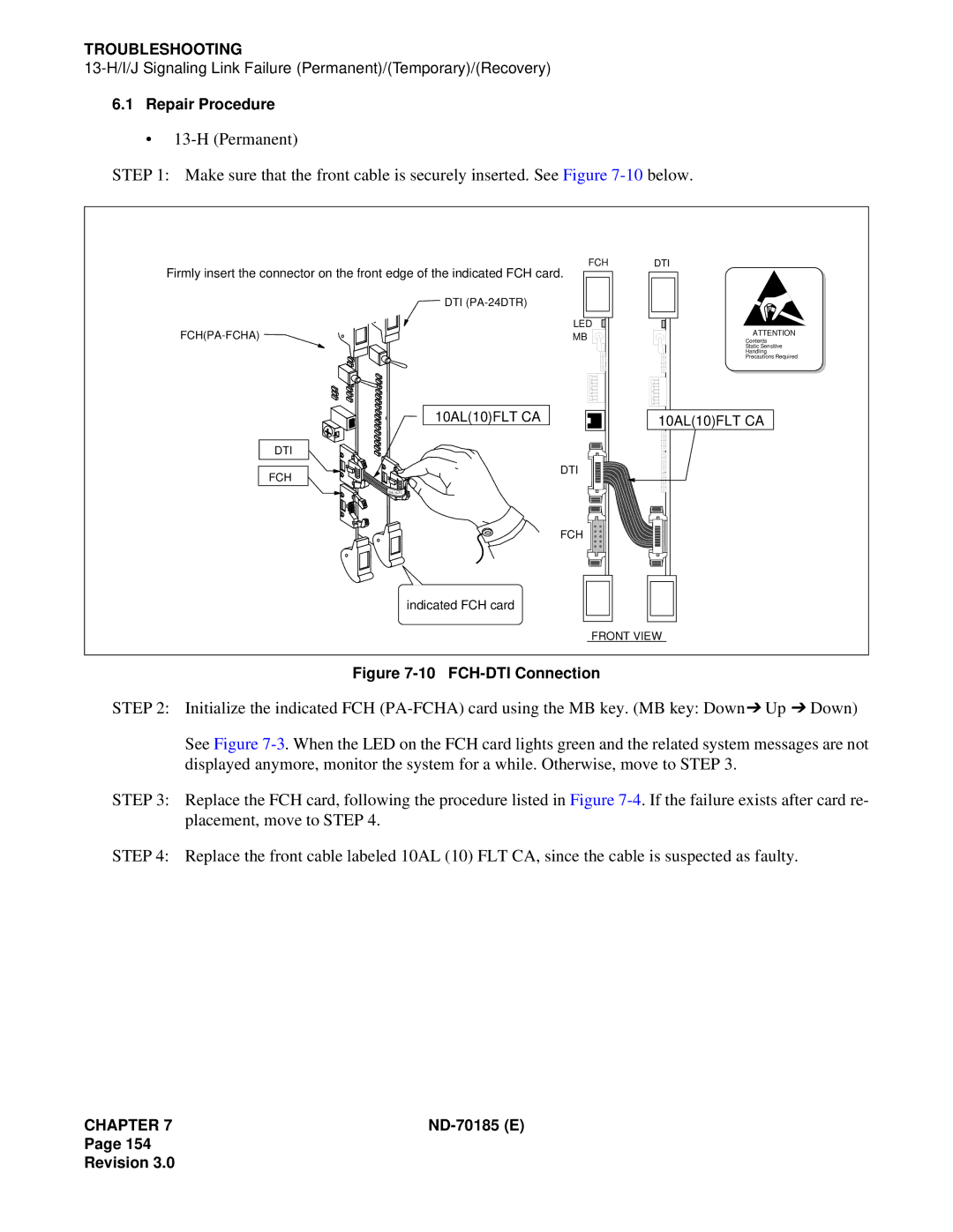
STEP 1: Make sure that the front cable is securely inserted. See Figure
FCH
Firmly insert the connector on the front edge of the indicated FCH card.
DTI
LED
MB |
10AL(10)FLT CA
![]() DTI
DTI
DTI
ATTENTION
Contents
Static Sensitive
Handling
Precautions Required
10AL(10)FLT CA
FCH
DTI
![]()
![]() 10AL
10AL ![]()
FCH
indicated FCH card
FRONT VIEW
Figure 7-10 FCH-DTI Connection
STEP 2: Initialize the indicated FCH
See Figure
STEP 3: Replace the FCH card, following the procedure listed in Figure
STEP 4: Replace the front cable labeled 10AL (10) FLT CA, since the cable is suspected as faulty.
CHAPTER 7 |
Page 154
Revision 3.0