POST INSTALLATION TEST
Repair Procedure When LED Indicates Abnormality
All 24
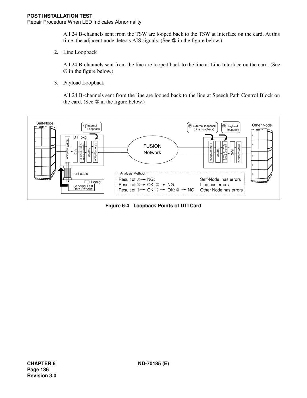
2.Line Loopback
All 24
3.Payload Loopback
All 24
|
| 1 Internal |
|
|
| 2 | External loopback |
| 3 | Payload | Other Node | |||
|
|
|
|
|
|
| ||||||||
|
|
| Loopback |
|
|
|
| (Line Loopback) |
|
| loopback | |||
TDSW Interface | DTI pkg |
|
|
|
|
|
|
|
|
|
|
| ||
PAD | Speech Path Control Block | Framer | Line Interface |
| FUSION |
|
|
| Line Interface | Framer | Speech Path Control Block | PAD | TDSW Interface | |
| Network |
|
|
| ||||||||||
|
|
|
|
| ||||||||||
| front cable |
| Analysis Method |
|
|
|
|
|
|
|
| |||
|
|
| FCH card | Result of ➀ | NG: |
|
|
| has errors | |||||
|
|
| Result of ➀ | OK, ➁ | NG: |
|
| Line has errors |
| |||||
| Sending Test |
|
|
|
| |||||||||
| Data Pattern |
| Result of ➀ | OK, ➁ | OK: ➂ | NG: | Other Node has errors | |||||||
Figure 6-4 Loopback Points of DTI Card
CHAPTER 6 |
Page 136
Revision 3.0