INSTALLATION
Connecting Cables
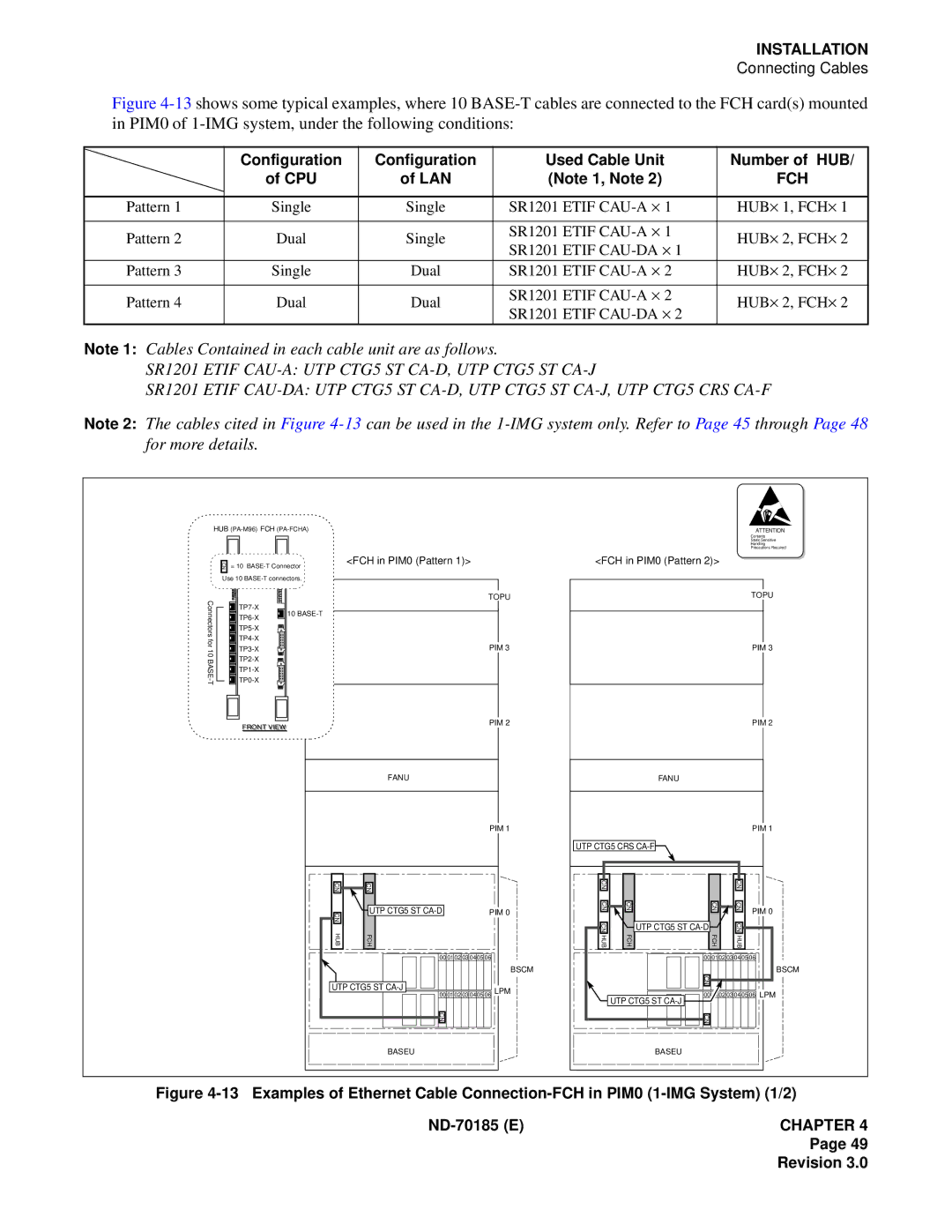
Figure 4-13 shows some typical examples, where 10 BASE-T cables are connected to the FCH card(s) mounted in PIM0 of 1-IMG system, under the following conditions:
| Configuration | Configuration | Used Cable Unit |
| Number of HUB/ | ||||
| of CPU | of LAN | (Note 1, Note 2) |
|
|
| FCH |
| |
|
|
|
|
|
|
|
|
| |
Pattern 1 | Single | Single | SR1201 ETIF | 1 |
| HUB⋅ | 1, FCH⋅ | 1 | |
|
|
|
|
|
|
|
|
| |
Pattern 2 | Dual | Single | SR1201 ETIF | 1 |
| HUB⋅ | 2, FCH⋅ | 2 | |
SR1201 ETIF | ⋅ | 1 | |||||||
|
|
|
|
|
| ||||
|
|
|
|
|
|
|
|
| |
Pattern 3 | Single | Dual | SR1201 ETIF | 2 |
| HUB⋅ | 2, FCH⋅ | 2 | |
|
|
|
|
|
|
|
|
| |
Pattern 4 | Dual | Dual | SR1201 ETIF | 2 |
| HUB⋅ | 2, FCH⋅ | 2 | |
SR1201 ETIF | ⋅ | 2 | |||||||
|
|
|
|
|
| ||||
Note 1: Cables Contained in each cable unit are as follows.
SR1201 ETIF
SR1201 ETIF
Note 2: The cables cited in Figure
HUB |
| |
CN | = 10 | <FCH in PIM0 (Pattern 1)> |
| ||
Use 10
Connectors |
| TOPU | |
10 | |||
| |||
|
| ||
|
| ||
for |
| ||
PIM 3 | |||
10 | |||
| |||
| |||
| |||
|
| ||
| FRONT VIEWI | PIM 2 | |
|
|
FANU
PIM 1
CN | CN |
|
CN | UTP CTG5 ST | PIM 0 |
|
| |
HUB | FCH |
|
00 0102 03 04 05 06 |
|
| BSCM |
UTP CTG5 ST | LPM |
00 0102 03 04 05 06 |
CN
ATTENTION
Contents
Static Sensitive
Handling
Precautions Required
<FCH in PIM0 (Pattern 2)>
TOPU
PIM 3
PIM 2
FANU
PIM 1
UTP CTG5 CRS |
CN |
|
| CN |
|
CN | CN | CN | CN | PIM 0 |
|
|
|
| |
CN | FCH | UTP CTG5 ST | CN |
|
HUB | FCH | HUB |
| |
|
| 00 0102 03 04 05 06 | ||
BSCM
|
|
|
|
|
| CN |
|
| ||||||
|
|
|
|
|
|
|
|
|
|
|
|
|
|
|
|
|
|
|
|
|
|
|
|
|
|
|
|
|
|
|
|
|
|
|
|
|
|
|
|
|
|
|
| LPM |
UTP CTG5 | ST |
|
|
| 00 | 01 | 02 | 03 | 04 | 05 | 06 | |||
|
|
|
|
|
|
|
|
|
| |||||
|
|
|
|
|
|
|
|
|
|
|
| |||
|
|
|
|
|
| CN |
|
|
|
|
|
|
|
|
|
|
|
|
|
|
|
|
|
|
|
|
|
|
|
|
|
|
|
|
|
|
|
|
|
|
|
|
|
|
BASEU
BASEU
Figure 4-13 Examples of Ethernet Cable Connection-FCH in PIM0 (1-IMG System) (1/2)
ND-70185 (E)CHAPTER 4
Page 49