Chapter 1 Introduction
Front Panel
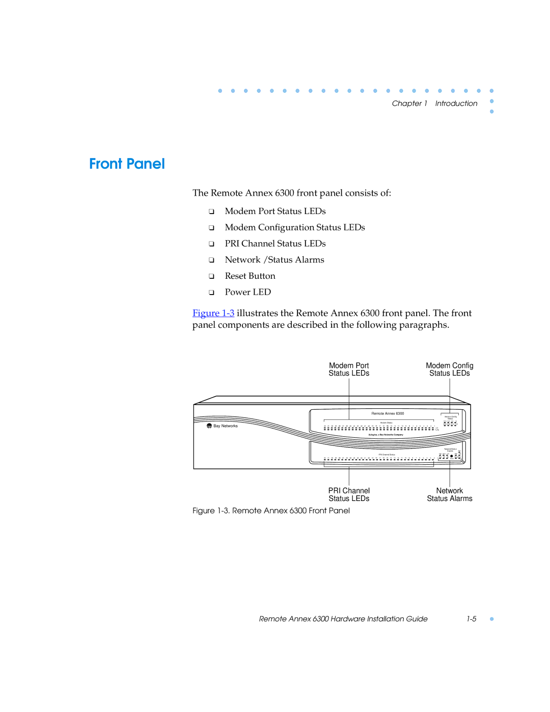
The Remote Annex 6300 front panel consists of:
❑Modem Port Status LEDs
❑Modem Configuration Status LEDs
❑PRI Channel Status LEDs
❑Network /Status Alarms
❑Reset Button
❑Power LED
Figure 1-3 illustrates the Remote Annex 6300 front panel. The front panel components are described in the following paragraphs.
Modem Port | Modem Config |
Status LEDs | Status LEDs |
Remote Annex 6300
Modem Config
Status
 Bay Networks
Modem Status
|
|
|
|
|
|
|
|
|
|
|
|
|
|
|
|
|
|
|
|
|
|
|
|
|
|
|
|
|
|
|
|
|
| |||
32 | 31 | 30 | 29 | 28 | 27 | 26 | 25 | 24 | 23 | 22 | 21 | 20 | 19 | 18 | 17 | 16 | 15 | 14 | 13 | 12 | 11 | 10 | 9 | 8 | 7 | 6 | 5 | 4 | 3 | 2 | 1 | CD |
|
|
| |
|
|
|
|
|
|
|
|
|
|
|
|
|
|
|
|
|
|
|
|
|
|
|
|
|
|
|
|
|
|
|
|
|
|
| ||
|
|
|
|
|
|
|
|
|
|
|
|
|
|
|
|
|
|
|
|
|
|
|
|
|
|
|
|
|
|
|
| Tx/Rx |
|
|
| |
|
|
|
|
|
|
|
|
|
|
|
|
| Xylogics, a Bay Networks Company |
|
|
|
|
|
|
|
|
|
|
|
|
|
| |||||||||
|
|
|
|
|
|
|
|
|
|
|
|
|
|
|
|
|
|
|
|
|
|
|
|
|
|
|
|
|
|
|
|
|
| Network/Status | ||
|
|
|
|
|
|
|
|
|
|
|
|
|
|
|
|
|
|
|
|
|
|
|
|
|
|
|
|
|
|
|
|
|
|
| Ararms | Attn |
|
|
|
|
|
|
|
|
|
|
|
|
|
|
|
| PRI Channel Status |
|
|
|
|
|
|
|
|
|
|
|
|
| Test | Sync | Los | Stat Traf | |||
|
|
|
|
|
|
|
|
|
|
|
|
|
|
|
|
|
|
|
|
|
|
|
|
|
|
|
|
|
|
|
|
| ||||
32 | 31 | 30 | 29 | 28 | 27 | 26 | 25 | 24 | 23 | 22 | 21 | 20 | 19 | 18 | 17 | 16 | 15 | 14 | 13 | 12 | 11 | 10 | 9 | 8 | 7 | 6 | 5 | 4 | 3 | 2 | 1 |
| Red | Yel | Blu | Setup Power |
|
|
| Reset |
| ||||||||||||||||||||||||||||||||
|
|
|
|
|
|
|
|
|
|
|
|
|
|
|
|
|
|
|
|
|
|
|
|
|
|
|
|
|
|
|
|
|
|
|
|
|
|
|
|
|
|
|
|
|
|
|
|
|
|
|
|
|
|
|
|
|
|
|
|
|
|
|
|
|
|
|
|
|
|
|
|
|
|
PRI Channel | Network |
Status LEDs | Status Alarms |
Figure 1-3. Remote Annex 6300 Front Panel
Remote Annex 6300 Hardware Installation Guide |