CPM1A
CPM1A Programmable Controllers
Omron Product References
Omron
Table of Contents
Appendices
About this Manual
Precautions
Intended Audience
General Precautions
Safety Precautions
Operating Environment Precautions
Application Precautions
Xiv
Application Precautions
Backup method Data
EC Directives
Applicable Directives
Concepts
Conformance to EC Directives
Xviii
Section
Section
CPM1A Features and Functions
1 CPM1A Features
Using the PT
NT Link Communications CompoBus/S I/O Link Units
Standard Peripheral Devices
Programming is Possible
2 I/O Terminal and IR Bit Allocation
CPU Units
Expansion I/O Units
Unit Relay output Transistor output Sink type Source type
Set value Word Word 001 or later
Control Corresponding IR word Setting range BCD
3 CPM1A Functions
PC model Input bits Response time
Mode Function
PC model Input bits Min. input pulse width
Pulse output single-phase output
Temperature Sensor Unit Functions
CompoBus/S Slave Functions CPM1A-SRT21
System Configuration
CPU Unit and Expansion I/O Unit Configuration
CPU Unit and Expansion Unit
CPM1A CPU Units
Expansion I/O Units
Unit Max. number Inputs Outputs Model Units
Host Link Communications
Expansion Units
Connecting to a
Programmable Terminal
Name Usage Model number
One-to-one PC Link Communications
Adapters and Cables
Name Specifications
One-to-one NT Link Communications
CompoBus/S I/O Link Connections
Peripheral Device Connections
Sysmac Support Software SYSMAC-CPT Support
Name Model number
Revised Specifications
Previous specifications New specifications Relevant pages
Unit Specifications and Components
CPM1A-10CDR-j CPM1A-20CDR-j CPM1A-30CDR-j CPM1A-40CDR-j
Specifications
General Specifications
Characteristics
Memory Backup
3 I/O Specifications
CPU Unit Input Specifications
Increment Mode 5 kHz Max
Specification
Expansion I/O Unit Input Specifications
CPU Unit and Expansion I/O Unit Output Specifications
Relay Output
Transistor Output Sink Type
Transistor Output Source Type
20EDT 8ET
10CDT1-D 20CDT1-D 30CDT1-D 40CDT1-D 20EDT1 8ET1
RS-422 Adapter Specifications
Communications Adapter Specifications
RS-232C Adapter Specifications
Unit Components
CPU Unit Components
CPM1A-10CDR-j/10CDT-D/10CDT1-D 10 I/O Terminals
CPM1A-40CDR-j/40CDT-D/40CDT1-D 40 I/O Terminals
CPU Unit Component Descriptions
Indicator Status Meaning
Fatal error Input indicators
Expansion I/O Unit Components
Expansion I/O Unit with 20 I/O Terminals
Expansion I/O Unit with 8 Input Terminals
Expansion I/O Unit with 8 Output Terminals
Temperature Sensor Unit Components
Analog I/O Unit Components
CPM1A-TS001/002
CPM1A-TS101/102
Set value Thermocouple Range C Range F
Set value Platinum resistance Range C Range F
Pins Function
CompoBus/S I/O Link Unit Components
RS-422 Adapter
Communications Adapter Components
RS-232C Adapter
Installation and Wiring
Design Precautions
Power Supply Wiring
Power Supply Voltage
4 CPM1A Power Interruptions
Selecting an Installation Site
Installation Site Conditions
Momentary Power Failure Detection
Automatic Restart
Checking the Program
Delete END
00178CIRCUIT ERR
Corrected Program
11 Bit, Digit, Word Monitor
Bit Monitor
Cont
Word Monitor
CLR Channel LR
Multiple Address Monitoring
Channel LR
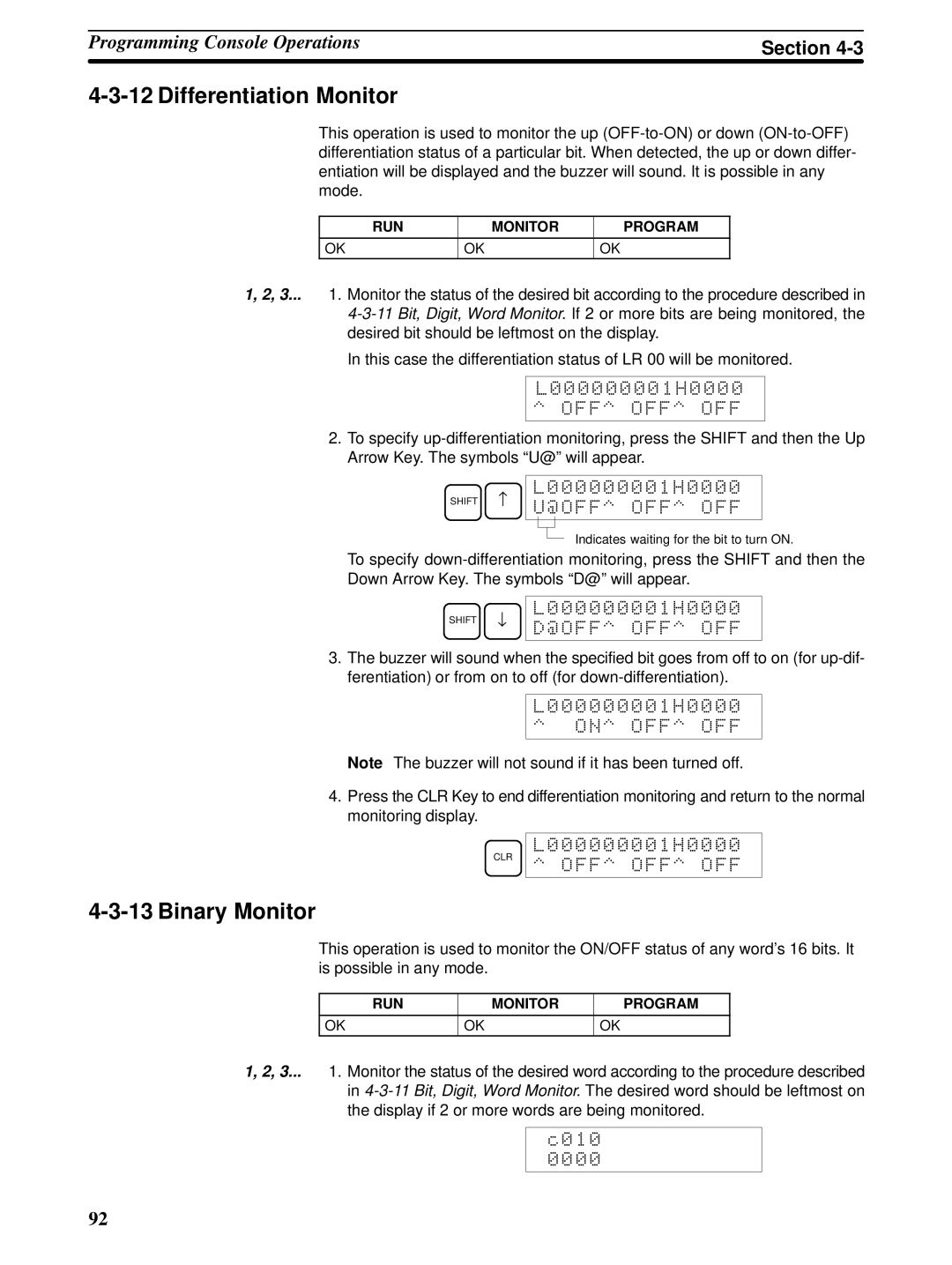
Differentiation Monitor
Binary Monitor
@OFF OFF OFF
CLR OFF OFF OFF
Three-word Monitor
Signed Decimal Monitor
Unsigned Decimal Monitor
3CH CHG?
Changing Timer, Counter SV
Three-word Data Modification
Incrementing and Decrementing a Constant
Hexadecimal, BCD Data Modification
Inputting a New SV Constant
Montr
Binary Data Modification
Pres VAL?
Signed Decimal Data Modification
D0000 Montr
Force Set, Reset
Unsigned Decimal Data Modification
Clear Force Set/Reset
Hex-ASCII Display Change
On on
00000FORCE RELE?
Program Password
Programming Example
Displaying the Cycle Time
Preparatory Operations
00000MEMORY CLR? HR CNT DM Montr END HR CNT DM
Programming Procedures
Example Program
Programming Procedures
Inputting the One-second Timer
Inputting the Self-holding Bit
Write NOP
Inputting the Two-second Timer
Inputting the 10-count Counter
Inputting the END001 Instruction
LD not
Inputting the Flicker Output
Test Run in Monitor Mode
Monitor BZ
Test Runs and Error Processing
Initial System Checks and Test Run Procedure
2 CPM1A Test Run Procedure
Initial System Checks
Points to check
Flash Memory Precautions
Error
CPM1A Cycle
Non-fatal Errors
Fatal Errors
Self-diagnosis Functions
Message FAL No Meaning and appropriate response
Identifying Errors
User-defined Errors
Error Messages
Error Flags
Programming Console Operation Errors
Programming Errors
FALS07
Message MSG46
Type Message Meaning and appropriate response
Circuit ERR
Troubleshooting Flowcharts
Main Check
Power Supply Check
Fatal Error Check
Follow the Memory Error
Non-fatal Error Check
121
122
Environmental Conditions Check
Memory Error Check
Maintenance Inspections
Power supply Allowable voltage fluctuation range
Inspection Items
Inspection items Details Criteria Remarks
Handling Precautions
Necessary Tools for Inspection
Standard Tools
Measurement Devices
Expansion Memory Unit
Precautions
Overview
Memory Areas
Button
Nomenclature
Specifications and Nomenclature
Specifications
LED Indicator
Handling
Mounting/Removing Eeprom
Mounting Eeprom
Peripheral Port Communications Settings
PC Connections
CPM1, CPM1A, CPM2A
CQM1, and SRM1 PCs
Disconnecting
Uploading Programs
Operation Procedure
Downloading Programs
134
135
Standard Models
Expansion Units
CPU Units
Expansion I/O Units
Temperature Sensor Units
Description Specifications Model number
CompoBus/S I/O Link Unit
Communications Adapters
Name Appearance Model Number Specifications
Peripheral Devices
Dimensions
CPM1A-10CDR-j/10CDT-D/10CDT1-D CPU Unit
CPM1A-20CDR-j/20CDT-D/20CDT1-D CPU Unit
CPM1A-30CDR-j/30CDT-D/30CDT1-D CPU Unit
CPM1A-8jjjExpansion I/O Unit
CPM1A-40CDR-j/40CDT-D/40CDT1-D CPU Unit
CPM1A-20EDjExpansion I/O Unit
CPM1A-SRT21 CompoBus/S I/O Link Unit
CPM1A-TSjjjTemperature Sensor Unit
CPM1A-MAD01 Analog I/O Unit
CPM1-CIF01 RS-232C Adapter
CPM1-CIF11 RS-422 Adapter
Dimensions with Peripheral Devices Attached
Appendix B
ACP
Ascii
AUTOEXEC.BAT
BCD
Bit designator
Bit number
Bit-control instruction
Block
CONFIG.SYS
CTS
Default
DIP switch
Data link
Data link area
Eeprom
Eprom
FCS
Delay
Initialization error
Input signal
Install
JIS
LED
LSS
Not
OFF
PCB
RAS
Prom
RAM
ROM
SCP
SSS
Syntax error
System configuration
System error
System error message
WDT
Numbers
Index
165
166
167
Revision code Date Revised content
Revision History
 L000000001H0000