Specifications |
|
|
|
| Section | ||
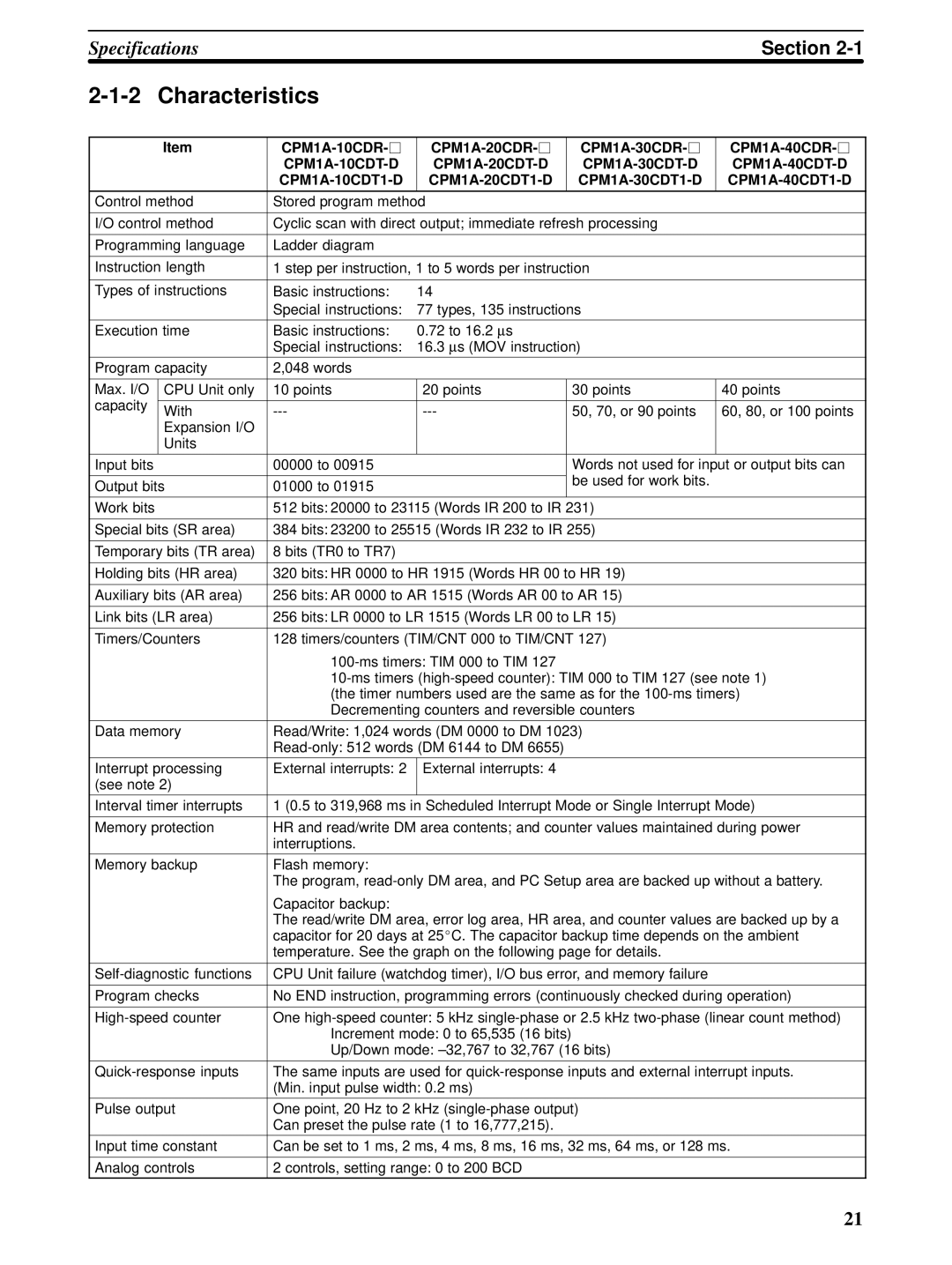
Characteristics |
|
|
|
|
| ||
|
|
|
|
|
|
|
|
| Item |
|
| ||||
|
|
| |||||
|
| ||||||
|
|
|
|
|
|
| |
Control method | Stored program method |
|
|
| |||
|
|
|
| ||||
I/O control method | Cyclic scan with direct output; immediate refresh processing |
|
| ||||
|
|
|
|
|
|
| |
Programming language | Ladder diagram |
|
|
|
|
| |
|
|
|
| ||||
Instruction length | 1 step per instruction, 1 to 5 words per instruction |
|
| ||||
|
|
|
|
|
|
| |
Types of instructions | Basic instructions: | 14 |
|
|
|
| |
|
| Special instructions: | 77 types, 135 instructions |
|
| ||
|
|
|
|
|
| ||
Execution time | Basic instructions: | 0.72 to 16.2 ∝ s |
|
|
| ||
|
| Special instructions: 16.3 ∝ s (MOV instruction) |
|
| |||
|
|
|
|
|
|
| |
Program capacity | 2,048 words |
|
|
|
|
| |
|
|
|
|
|
|
| |
Max. I/O | CPU Unit only | 10 points | 20 points |
| 30 points | 40 points | |
capacity |
|
|
|
|
|
|
|
With |
| 50, 70, or 90 points | 60, 80, or 100 points | ||||
|
| ||||||
| Expansion I/O |
|
|
|
|
|
|
| Units |
|
|
|
|
|
|
|
|
|
|
|
|
|
|
Input bits |
| 00000 to 00915 |
|
| Words not used for input or output bits can | ||
|
|
|
|
| be used for work bits. |
|
|
Output bits | 01000 to 01915 |
|
|
|
| ||
|
|
|
|
| |||
|
|
|
|
|
| ||
Work bits |
| 512 bits: 20000 to 23115 (Words IR 200 to IR 231) |
|
| |||
|
|
|
| ||||
Special bits (SR area) | 384 bits: 23200 to 25515 (Words IR 232 to IR 255) |
|
| ||||
|
|
|
|
|
|
| |
Temporary bits (TR area) | 8 bits (TR0 to TR7) |
|
|
|
|
| |
|
|
|
| ||||
Holding bits (HR area) | 320 bits: HR 0000 to HR 1915 (Words HR 00 to HR 19) |
|
| ||||
|
|
|
| ||||
Auxiliary bits (AR area) | 256 bits: AR 0000 to AR 1515 (Words AR 00 to AR 15) |
|
| ||||
|
|
|
| ||||
Link bits (LR area) | 256 bits: LR 0000 to LR 1515 (Words LR 00 to LR 15) |
|
| ||||
|
|
|
| ||||
Timers/Counters | 128 timers/counters (TIM/CNT 000 to TIM/CNT 127) |
|
| ||||
|
|
|
|
| |||
|
| ||||||
|
| (the timer numbers used are the same as for the | |||||
|
| Decrementing counters and reversible counters |
|
| |||
|
|
|
| ||||
Data memory | Read/Write: 1,024 words (DM 0000 to DM 1023) |
|
| ||||
|
|
|
|
| |||
Interrupt processing | External interrupts: 2 | External interrupts: 4 |
|
|
| ||
(see note 2) |
|
|
|
|
|
| |
Interval timer interrupts | 1 (0.5 to 319,968 ms in Scheduled Interrupt Mode or Single Interrupt Mode) | ||||||
|
|
| |||||
Memory protection | HR and read/write DM area contents; and counter values maintained during power | ||||||
|
| interruptions. |
|
|
|
|
|
|
|
|
|
|
|
| |
Memory backup | Flash memory: |
|
|
|
|
| |
|
| The program, | |||||
|
| Capacitor backup: |
|
|
|
|
|
|
| The read/write DM area, error log area, HR area, and counter values are backed up by a | |||||
|
| capacitor for 20 days at 25_C. The capacitor backup time depends on the ambient | |||||
|
| temperature. See the graph on the following page for details. |
|
| |||
|
|
|
| ||||
CPU Unit failure (watchdog timer), I/O bus error, and memory failure |
|
| |||||
|
|
| |||||
Program checks | No END instruction, programming errors (continuously checked during operation) | ||||||
|
|
| |||||
One | |||||||
|
| Increment mode: 0 to 65,535 (16 bits) |
|
|
| ||
|
| Up/Down mode: |
|
| |||
|
|
| |||||
The same inputs are used for | |||||||
|
| (Min. input pulse width: 0.2 ms) |
|
|
| ||
Pulse output | One point, 20 Hz to 2 kHz |
|
| ||||
|
| Can preset the pulse rate (1 to 16,777,215). |
|
|
| ||
|
|
| |||||
Input time constant | Can be set to 1 ms, 2 ms, 4 ms, 8 ms, 16 ms, 32 ms, 64 ms, or 128 ms. | ||||||
|
|
|
|
| |||
Analog controls | 2 controls, setting range: 0 to 200 BCD |
|
|
| |||
21