Revision History
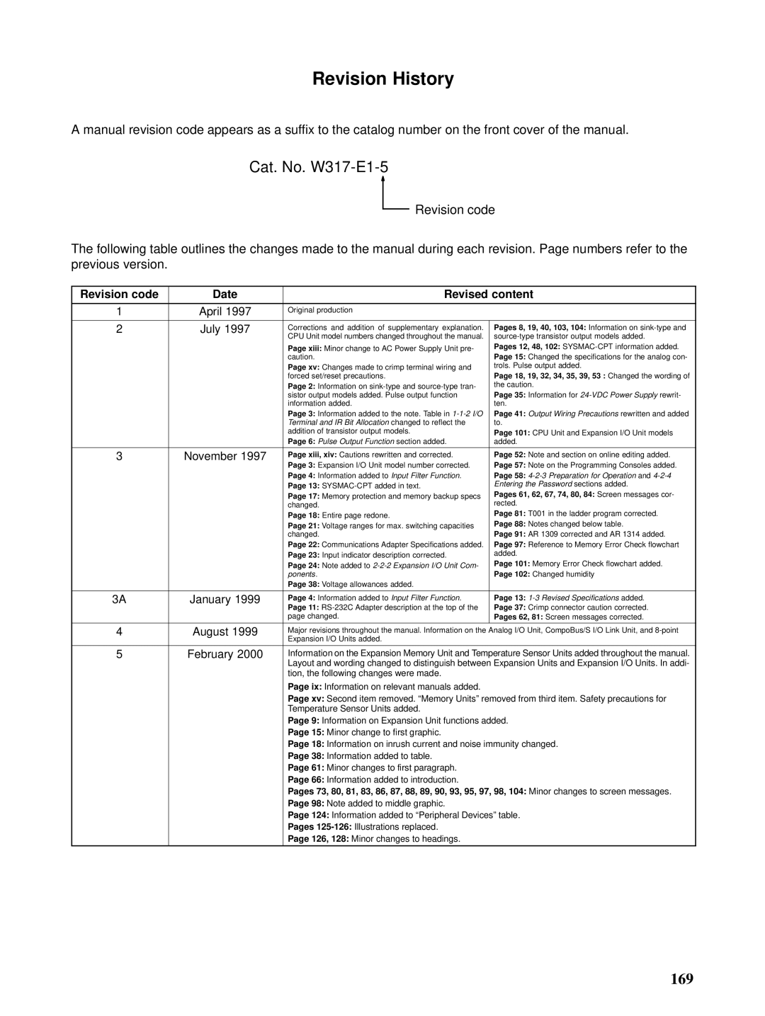
A manual revision code appears as a suffix to the catalog number on the front cover of the manual.
Cat. No. W317-E1-5
Revision code
The following table outlines the changes made to the manual during each revision. Page numbers refer to the previous version.
Revision code | Date | Revised content | |
|
|
|
|
1 | April 1997 | Original production |
|
|
|
|
|
2 | July 1997 | Corrections and addition of supplementary explanation. | Pages 8, 19, 40, 103, 104: Information on |
|
| CPU Unit model numbers changed throughout the manual. | |
|
| Page xiii: Minor change to AC Power Supply Unit pre- | Pages 12, 48, 102: |
|
| caution. | Page 15: Changed the specifications for the analog con- |
|
| Page xv: Changes made to crimp terminal wiring and | trols. Pulse output added. |
|
| forced set/reset precautions. | Page 18, 19, 32, 34, 35, 39, 53 : Changed the wording of |
|
| Page 2: Information on | the caution. |
|
| sistor output models added. Pulse output function | Page 35: Information for |
|
| information added. | ten. |
|
| Page 3: Information added to the note. Table in | Page 41: Output Wiring Precautions rewritten and added |
|
| Terminal and IR Bit Allocation changed to reflect the | to. |
|
| addition of transistor output models. | Page 101: CPU Unit and Expansion I/O Unit models |
|
| Page 6: Pulse Output Function section added. | added. |
|
|
|
|
3 | November 1997 | Page xiii, xiv: Cautions rewritten and corrected. | Page 52: Note and section on online editing added. |
|
| Page 3: Expansion I/O Unit model number corrected. | Page 57: Note on the Programming Consoles added. |
|
| Page 4: Information added to Input Filter Function. | Page 58: |
|
| Page 13: | Entering the Password sections added. |
|
| Page 17: Memory protection and memory backup specs | Pages 61, 62, 67, 74, 80, 84: Screen messages cor- |
|
| changed. | rected. |
|
| Page 18: Entire page redone. | Page 81: T001 in the ladder program corrected. |
|
| Page 21: Voltage ranges for max. switching capacities | Page 88: Notes changed below table. |
|
| changed. | Page 91: AR 1309 corrected and AR 1314 added. |
|
| Page 22: Communications Adapter Specifications added. | Page 97: Reference to Memory Error Check flowchart |
|
| Page 23: Input indicator description corrected. | added. |
|
| Page 24: Note added to | Page 101: Memory Error Check flowchart added. |
|
| ponents. | Page 102: Changed humidity |
|
| Page 38: Voltage allowances added. |
|
|
|
|
|
3A | January 1999 | Page 4: Information added to Input Filter Function. | Page 13: |
|
| Page 11: | Page 37: Crimp connector caution corrected. |
|
| page changed. | Pages 62, 81: Screen messages corrected. |
|
|
|
|
4 | August 1999 | Major revisions throughout the manual. Information on the Analog I/O Unit, CompoBus/S I/O Link Unit, and | |
|
| Expansion I/O Units added. |
|
5 | February 2000 | Information on the Expansion Memory Unit and Temperature Sensor Units added throughout the manual. | |
|
| Layout and wording changed to distinguish between Expansion Units and Expansion I/O Units. In addi- | |
|
| tion, the following changes were made. |
|
|
| Page ix: Information on relevant manuals added. |
|
|
| Page xv: Second item removed. “Memory Units” removed from third item. Safety precautions for | |
|
| Temperature Sensor Units added. |
|
|
| Page 9: Information on Expansion Unit functions added. | |
|
| Page 15: Minor change to first graphic. |
|
|
| Page 18: Information on inrush current and noise immunity changed. | |
|
| Page 38: Information added to table. |
|
|
| Page 61: Minor changes to first paragraph. |
|
|
| Page 66: Information added to introduction. |
|
|
| Pages 73, 80, 81, 83, 86, 87, 88, 89, 90, 93, 95, 97, 98, 104: Minor changes to screen messages. | |
|
| Page 98: Note added to middle graphic. |
|
|
| Page 124: Information added to “Peripheral Devices” table. | |
|
| Pages |
|
|
| Page 126, 128: Minor changes to headings. |
|
|
|
|
|
169
