| Handling | Section |
Removing EEPROM | Lift up the lock lever and detach the EEPROM. | |
6-3-2 PC Connections
! Caution
! Caution
CPM1, CPM1A, CPM2A,
CQM1, and SRM1 (-V2)
PCs
Mount the EEPROM to the
Do not disconnect the
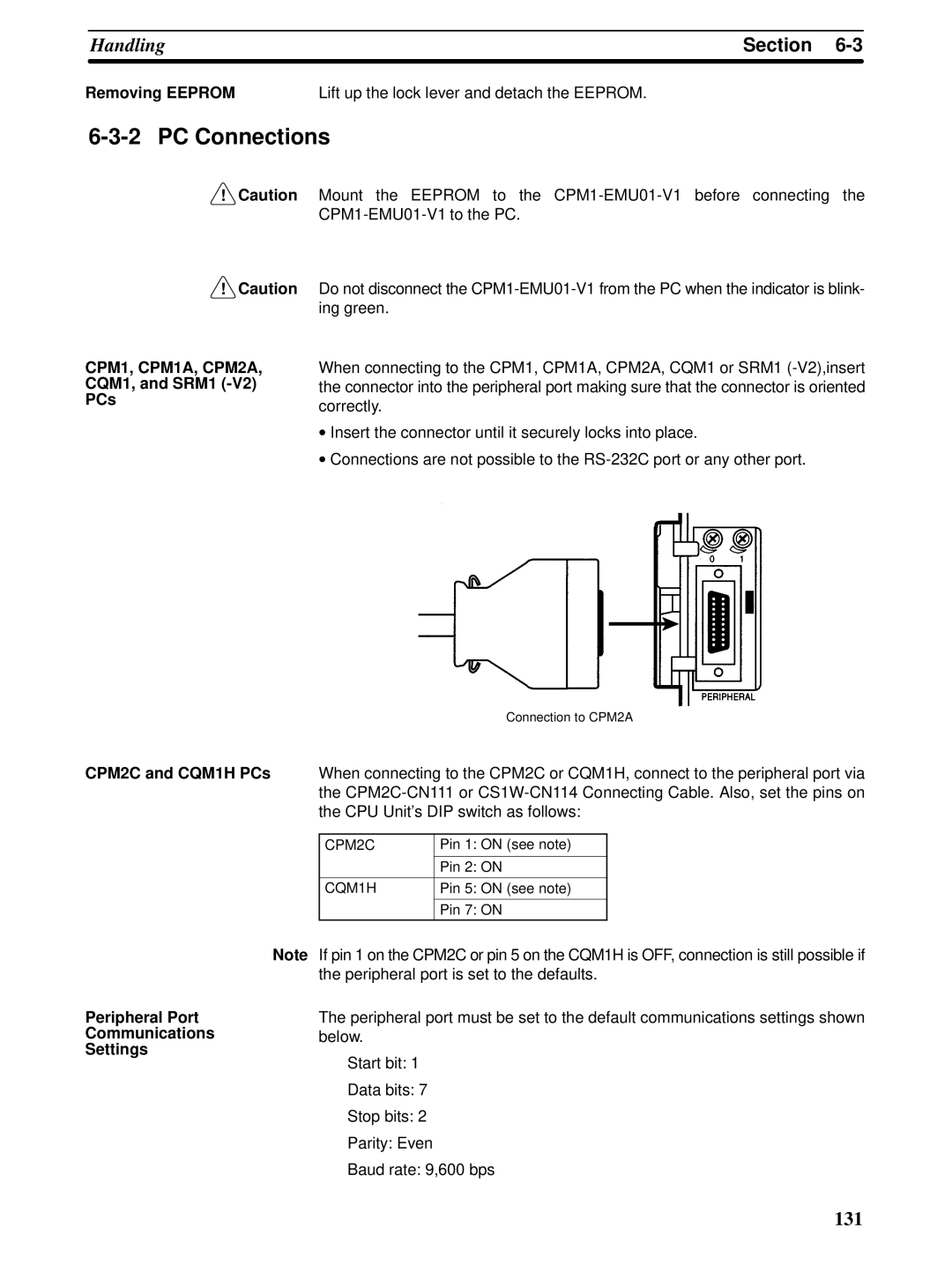
When connecting to the CPM1, CPM1A, CPM2A, CQM1 or SRM1
•Insert the connector until it securely locks into place.
•Connections are not possible to the
Connection to CPM2A
CPM2C and CQM1H PCs When connecting to the CPM2C or CQM1H, connect to the peripheral port via the
CPM2C | Pin 1: ON (see note) |
|
|
| Pin 2: ON |
|
|
CQM1H | Pin 5: ON (see note) |
|
|
| Pin 7: ON |
Peripheral Port
Communications
Settings
Note If pin 1 on the CPM2C or pin 5 on the CQM1H is OFF, connection is still possible if the peripheral port is set to the defaults.
The peripheral port must be set to the default communications settings shown below.
Start bit: 1
Data bits: 7
Stop bits: 2
Parity: Even
Baud rate: 9,600 bps
131