Unit Components | Section | |
|
|
|
2-2-5 CompoBus/S I/O Link Unit Components
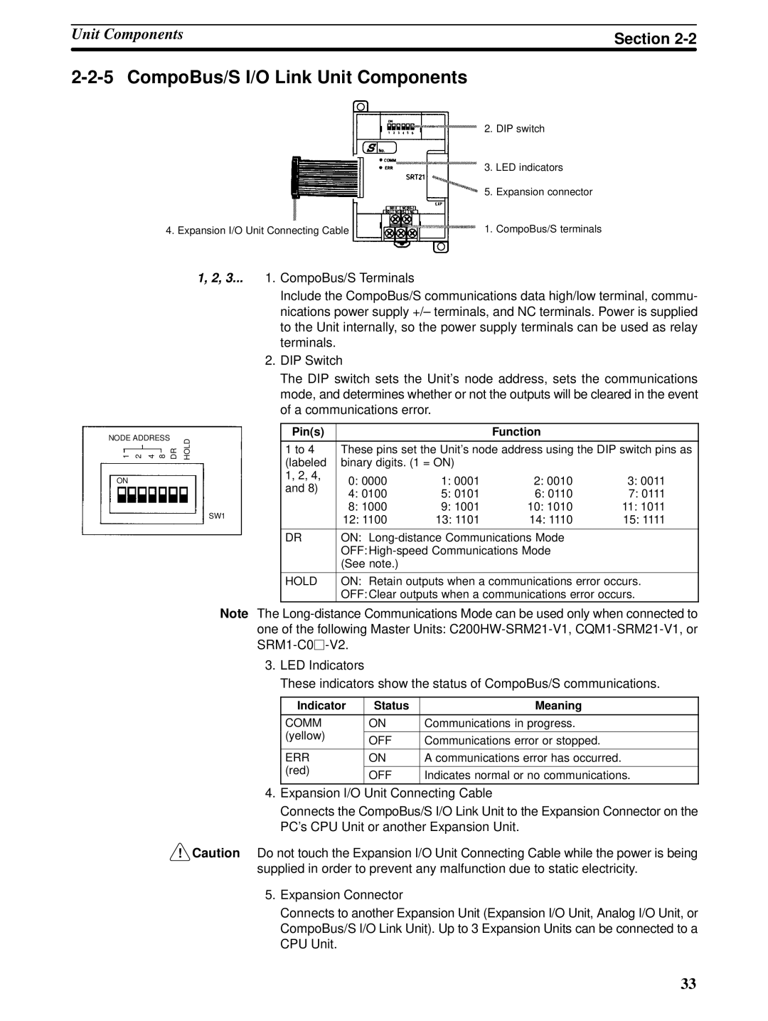
| 2. | DIP switch |
| 3. | LED indicators |
| 5. | Expansion connector |
4. Expansion I/O Unit Connecting Cable | 1. CompoBus/S terminals | |
1, 2, 3... 1. CompoBus/S Terminals
NODE ADDRESS |
| HOLD |
1 2 4 8 | DR |
ON
SW1
Note
! Caution
Include the CompoBus/S communications data high/low terminal, commu- nications power supply +/– terminals, and NC terminals. Power is supplied to the Unit internally, so the power supply terminals can be used as relay terminals.
2.DIP Switch
The DIP switch sets the Unit’s node address, sets the communications mode, and determines whether or not the outputs will be cleared in the event of a communications error.
Pin(s) |
|
| Function |
| |
|
| ||||
1 to 4 | These pins set the Unit’s node address using the DIP switch pins as | ||||
(labeled | binary digits. (1 = ON) |
|
| ||
1, 2, 4, | 0: 0000 | 1: 0001 | 2: 0010 | 3: 0011 | |
and 8) | |||||
4: 0100 | 5: 0101 | 6: 0110 | 7: 0111 | ||
| |||||
| 8: 1000 | 9: 1001 | 10: 1010 | 11: 1011 | |
| 12: 1100 | 13: 1101 | 14: 1110 | 15: 1111 | |
|
|
| |||
DR | ON: |
| |||
| OFF: |
| |||
| (See note.) |
|
|
| |
|
| ||||
HOLD | ON: Retain outputs when a communications error occurs. | ||||
| OFF: Clear outputs when a communications error occurs. | ||||
The
3.LED Indicators
These indicators show the status of CompoBus/S communications.
Indicator | Status | Meaning | |
|
|
| |
COMM | ON | Communications in progress. | |
(yellow) |
|
| |
OFF | Communications error or stopped. | ||
| |||
|
|
| |
ERR | ON | A communications error has occurred. | |
(red) |
|
| |
OFF | Indicates normal or no communications. | ||
| |||
|
|
|
4.Expansion I/O Unit Connecting Cable
Connects the CompoBus/S I/O Link Unit to the Expansion Connector on the PC’s CPU Unit or another Expansion Unit.
Do not touch the Expansion I/O Unit Connecting Cable while the power is being supplied in order to prevent any malfunction due to static electricity.
5. Expansion Connector
Connects to another Expansion Unit (Expansion I/O Unit, Analog I/O Unit, or CompoBus/S I/O Link Unit). Up to 3 Expansion Units can be connected to a CPU Unit.
33