Revised SpecificationsSection
Revised Specifications |
|
| ||
|
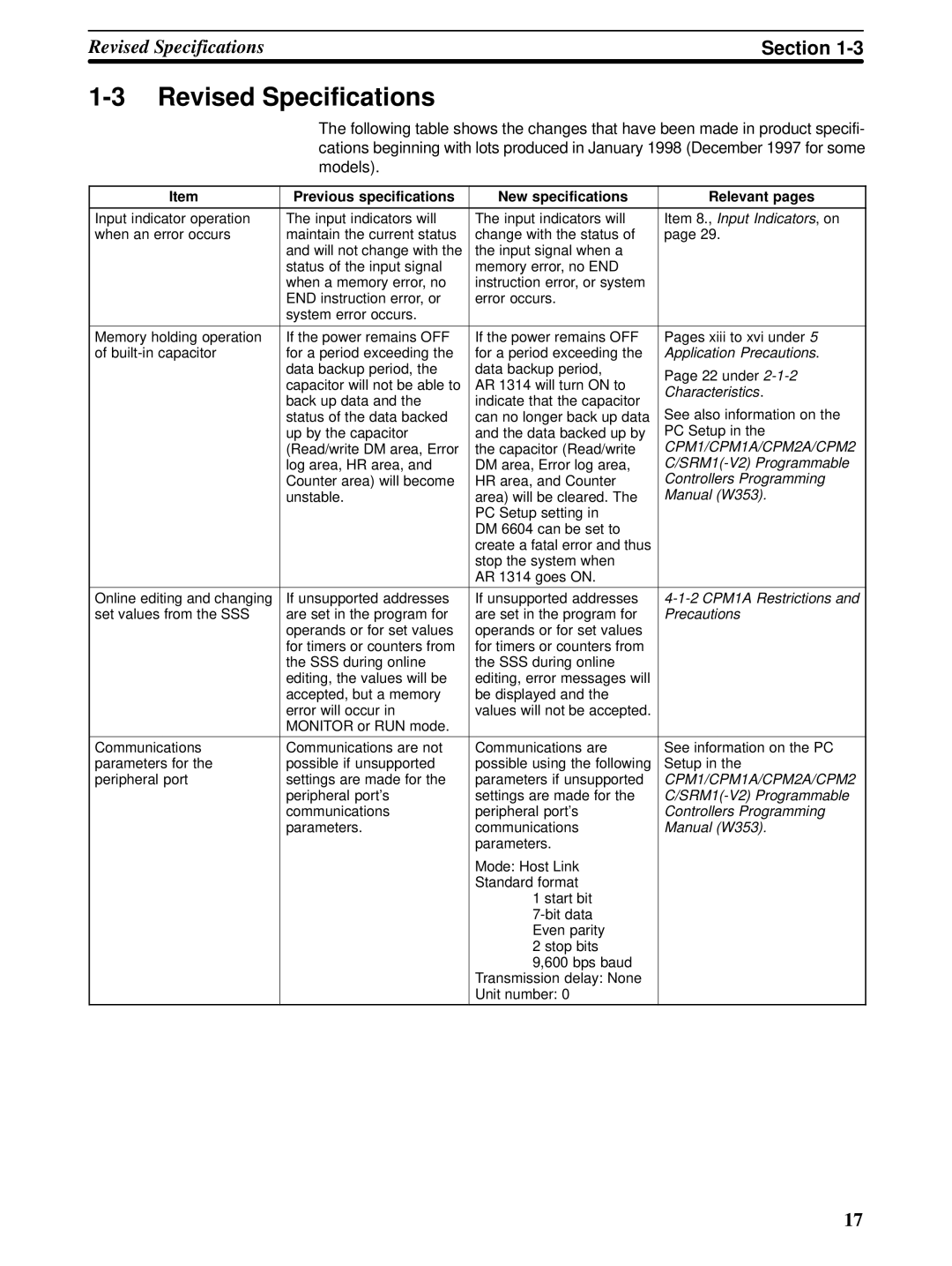
| The following table shows the changes that have been made in product specifi- | ||
|
| cations beginning with lots produced in January 1998 (December 1997 for some | ||
|
| models). |
|
|
|
|
|
|
|
| Item | Previous specifications | New specifications | Relevant pages |
|
|
|
| |
Input indicator operation | The input indicators will | The input indicators will | Item 8., Input Indicators, on | |
when an error occurs | maintain the current status | change with the status of | page 29. | |
|
| and will not change with the | the input signal when a |
|
|
| status of the input signal | memory error, no END |
|
|
| when a memory error, no | instruction error, or system |
|
|
| END instruction error, or | error occurs. |
|
|
| system error occurs. |
|
|
|
|
|
| |
Memory holding operation | If the power remains OFF | If the power remains OFF | Pages xiii to xvi under 5 | |
of | for a period exceeding the | for a period exceeding the | Application Precautions. | |
|
| data backup period, the | data backup period, | Page 22 under |
|
| capacitor will not be able to | AR 1314 will turn ON to | |
|
| Characteristics. | ||
|
| back up data and the | indicate that the capacitor | |
|
| See also information on the | ||
|
| status of the data backed | can no longer back up data | |
|
| up by the capacitor | and the data backed up by | PC Setup in the |
|
| (Read/write DM area, Error | the capacitor (Read/write | CPM1/CPM1A/CPM2A/CPM2 |
|
| log area, HR area, and | DM area, Error log area, | |
|
| Counter area) will become | HR area, and Counter | Controllers Programming |
|
| unstable. | area) will be cleared. The | Manual (W353). |
|
|
| PC Setup setting in |
|
|
|
| DM 6604 can be set to |
|
|
|
| create a fatal error and thus |
|
|
|
| stop the system when |
|
|
|
| AR 1314 goes ON. |
|
|
|
|
| |
Online editing and changing | If unsupported addresses | If unsupported addresses | ||
set values from the SSS | are set in the program for | are set in the program for | Precautions | |
|
| operands or for set values | operands or for set values |
|
|
| for timers or counters from | for timers or counters from |
|
|
| the SSS during online | the SSS during online |
|
|
| editing, the values will be | editing, error messages will |
|
|
| accepted, but a memory | be displayed and the |
|
|
| error will occur in | values will not be accepted. |
|
|
| MONITOR or RUN mode. |
|
|
Communications | Communications are not | Communications are | See information on the PC | |
parameters for the | possible if unsupported | possible using the following | Setup in the | |
peripheral port | settings are made for the | parameters if unsupported | CPM1/CPM1A/CPM2A/CPM2 | |
|
| peripheral port’s | settings are made for the | |
|
| communications | peripheral port’s | Controllers Programming |
|
| parameters. | communications | Manual (W353). |
|
|
| parameters. |
|
|
|
| Mode: Host Link |
|
|
|
| Standard format |
|
|
|
| 1 start bit |
|
|
|
|
| |
|
|
| Even parity |
|
|
|
| 2 stop bits |
|
|
|
| 9,600 bps baud |
|
|
|
| Transmission delay: None |
|
|
|
| Unit number: 0 |
|
17