Handling | Section |
6-2 Specifications and Nomenclature
6-2-1 Specifications
Item | Specifications |
|
|
Supported PCs | CPM1, CPM1A, CPM2A, CPM2C, SRM1 |
| CQM1, CQM1H |
|
|
Read/Write memory areas | User program: 15.2 Kwords max. |
| Data memory: DM 6144 to DM 6655 |
| |
| Expansion instructions: 18 instructions |
|
|
Connector | Connector compatible with CPM1, CPM1A, CPM2A, |
| SRM1 |
| For CPM2C and CQM1H PCs, connect via |
| |
|
|
Communications setting | 1 start bit, 7 data bits, even parity, 2 stop bits, |
| 9,600 bps |
|
|
EEPROM (See note 1.) | |
| ATMEL: AT28C256 |
| OMRON: |
|
|
Current consumption | 129 mA max. |
|
|
Dimensions | Main body (not including cables or connectors): |
| 57 ⋅ 92 ⋅ 38 mm (W ⋅ H ⋅ D) |
|
|
Weight | 200 g max. (not including EEPROM) |
Note 1. The EEPROM must be purchased separately.
2. For general specifications, refer to the relevant PC manual.
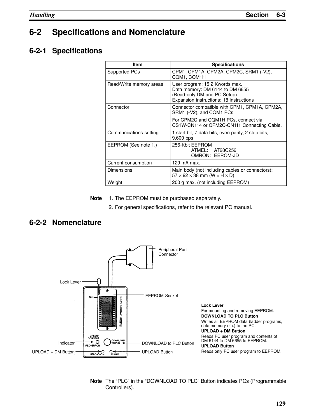
6-2-2 Nomenclature
Peripheral Port
Connector
Lock Lever
EEPROM Socket
Indicator | DOWNLOAD to PLC Button |
UPLOAD + DM Button | UPLOAD Button |
Lock Lever
For mounting and removing EEPROM.
DOWNLOAD TO PLC Button
Writes all EEPROM data (ladder programs, data memory etc.) to the PC.
UPLOAD + DM Button
Reads PC user program and contents of DM 6144 to DM 6655 to EEPROM.
UPLOAD Button
Reads only PC user program to EEPROM.
Note The “PLC” in the “DOWNLOAD TO PLC” Button indicates PCs (Programmable Controllers).
129