Wiring and ConnectionsSection
3-4-4 Input Wiring
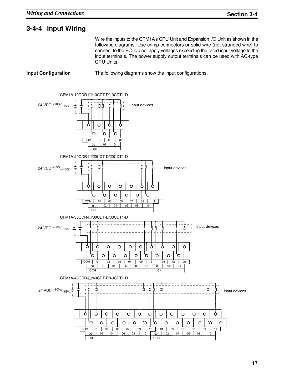
| Wire the inputs to the CPM1A’s CPU Unit and Expansion I/O Unit as shown in the |
| following diagrams. Use crimp connectors or solid wire (not stranded wire) to |
| connect to the PC. Do not apply voltages exceeding the rated input voltage to the |
| input terminals. The power supply output terminals can be used with |
| CPU Units. |
Input Configuration | The following diagrams show the input configurations. |
24 VDC | Input devices |
COM 01 03 05
00 02 04
0 CH
24 VDC | Input devices |
COM | 01 |
| 03 | 05 | 07 | 09 | 11 |
00 |
| 02 | 04 | 06 | 08 |
| 10 |
0 CH |
|
|
|
|
|
|
|
|
|
| |||||
24 VDC |
|
|
|
|
|
| Input devices |
COM | 01 |
| 03 | 05 | 07 | 09 | 11 | 01 | 03 | 05 |
00 |
| 02 | 04 | 06 | 08 | 10 |
| 00 | 02 | 04 |
0 CH |
|
|
|
|
|
|
| 1 CH |
|
|
|
|
|
|
|
| |||||
24 VDC |
|
|
|
|
|
|
|
|
| Input devices |
COM | 01 |
| 03 | 05 | 07 | 09 | 11 | 01 | 03 | 05 |
| 07 | 09 | 11 |
00 |
| 02 | 04 | 06 | 08 |
| 10 | 00 | 02 | 04 | 06 | 08 |
| 10 |
0 CH |
|
|
|
|
|
|
| 1 CH |
|
|
|
|
|
|
47