Installing the CPM1A | Section | |
|
|
|
Four, M4 holes |
|
100 mm CPU Unit |
|
A | 8 mm |
Use M4 dia. x 15 screws.
The width (A) between the mounting holes depends on the CPM1A model.
Model number | Width (A) | |
|
|
|
120 mm | ||
|
|
|
140 mm | ||
|
|
|
Expansion I/O Unit | 76 mm | |
|
|
|
| 56 mm | |
|
|
|
Analog I/O Unit |
| 56 mm |
|
|
|
CompoBus/S I/O Link Unit |
| 56 mm |
|
|
|
| 21 mm | |
|
|
|
| 21 mm | |
|
|
|
Temperature Sensor Unit |
| 76 mm |
Allow 10 to 15 mm between the Units when installing an Expansion Unit, Expan- sion I/O Unit, or Communications Adapter next to the CPU Unit, as shown below.
| 21 mm |
|
|
81 mm | CPU Unit |
| 100 mm |
Communications | 10 to | 10 to A | Expansion Unit or |
Expansion I/O Unit | |||
Adapter | 15 mm | 15 mm |
|
|
|
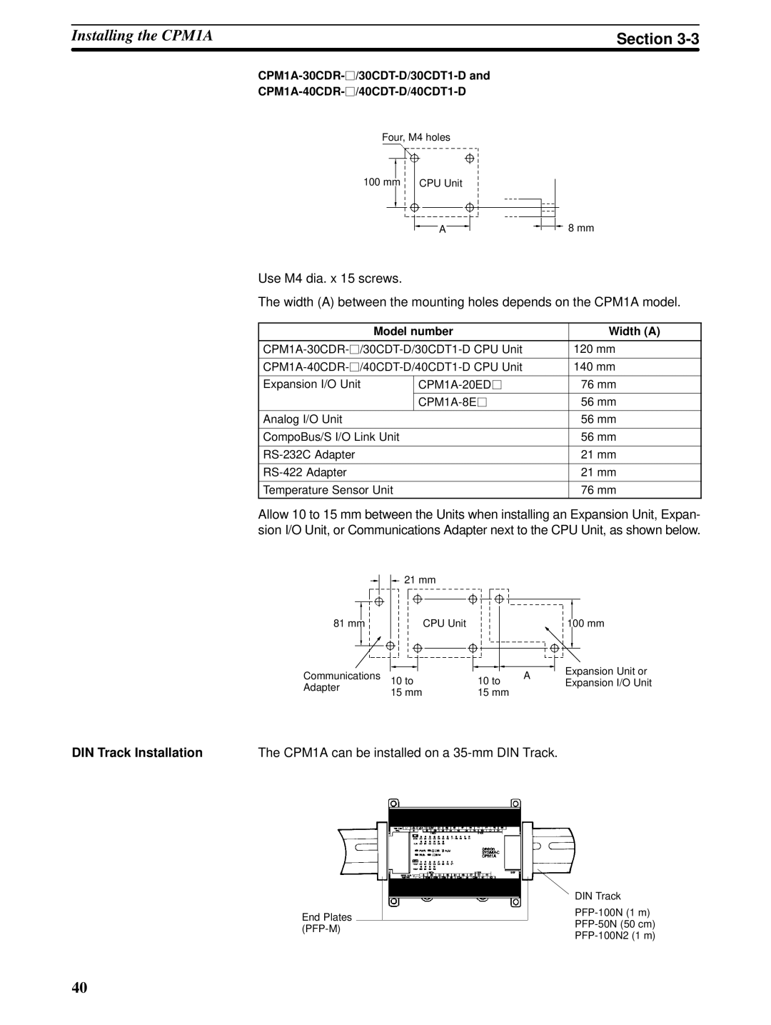
DIN Track Installation | The CPM1A can be installed on a |
| DIN Track | |
End Plates | ||
|
40