System Configuration |
| Section | |
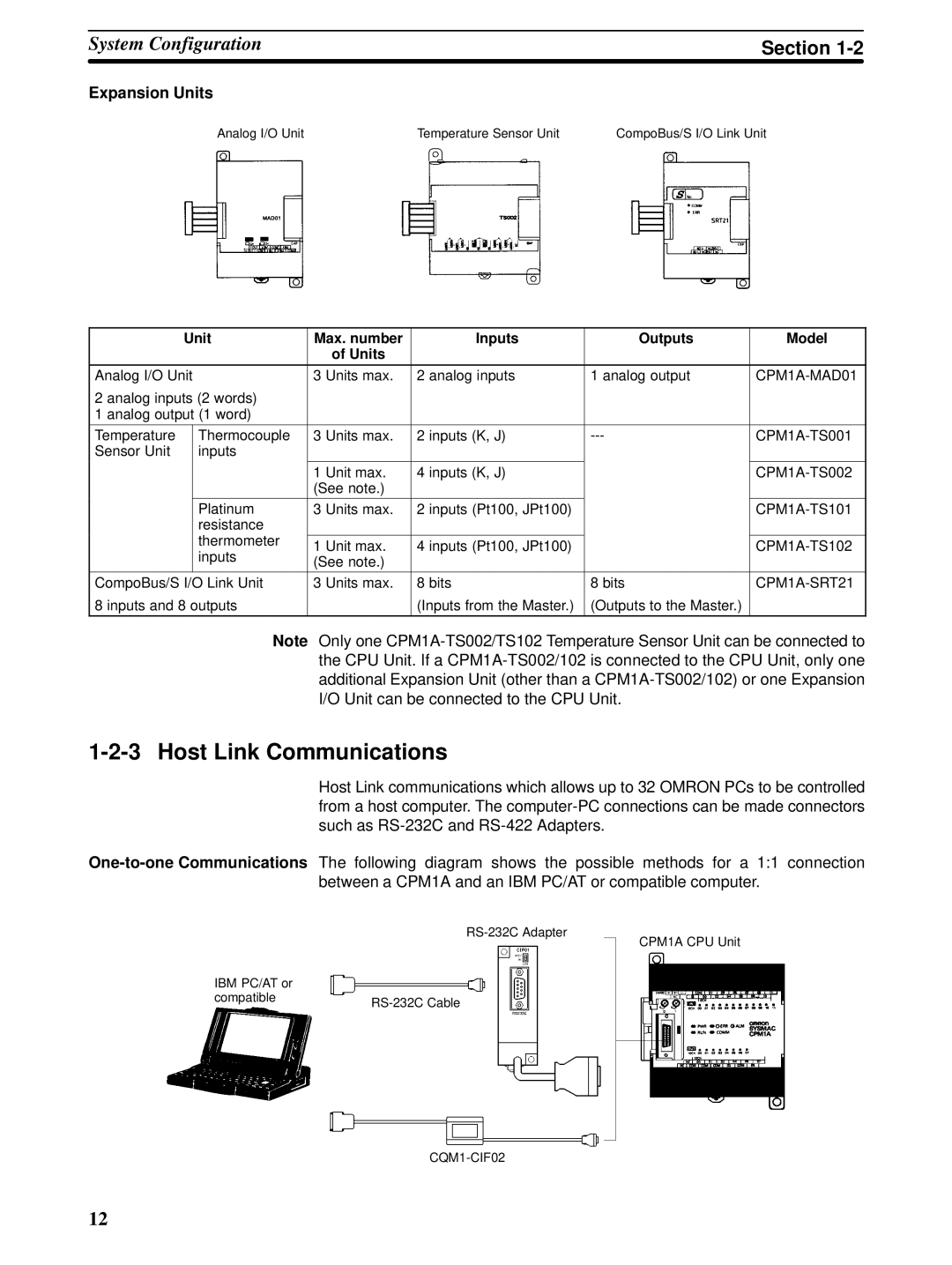
Expansion Units |
|
|
|
Analog I/O Unit | Temperature Sensor Unit | CompoBus/S I/O Link Unit | |
| Unit | Max. number | Inputs | Outputs | Model | ||
|
|
|
| of Units |
|
|
|
|
|
|
|
|
|
| |
Analog I/O Unit | 3 | Units max. | 2 analog inputs | 1 analog output | |||
2 analog inputs (2 words) |
|
|
|
|
| ||
1 analog output (1 word) |
|
|
|
|
| ||
Temperature |
| Thermocouple | 3 | Units max. | 2 inputs (K, J) | ||
Sensor Unit |
| inputs |
|
|
|
|
|
|
|
| 1 | Unit max. | 4 inputs (K, J) |
| |
|
|
| (See note.) |
|
|
| |
|
|
|
|
|
|
|
|
|
| Platinum | 3 | Units max. | 2 inputs (Pt100, JPt100) |
| |
|
| resistance |
|
|
|
|
|
|
| thermometer |
|
|
|
|
|
|
| 1 | Unit max. | 4 inputs (Pt100, JPt100) |
| ||
|
| inputs |
| ||||
|
| (See note.) |
|
|
| ||
|
|
|
|
|
| ||
CompoBus/S I/O Link Unit | 3 | Units max. | 8 bits | 8 bits | |||
8 inputs and 8 outputs |
|
| (Inputs from the Master.) | (Outputs to the Master.) |
| ||
|
|
|
|
|
|
|
|
Note Only one
1-2-3 Host Link Communications
Host Link communications which allows up to 32 OMRON PCs to be controlled from a host computer. The
IBM PC/AT or |
|
compatible | |
|
CPM1A CPU Unit
12