Pin Assignments
COM Port Interface
NOTE
The COM port connects to a PC for front panel emulation, to an ASCII terminal or printer for alarms, to a network device (e.g., a router) for SNMP applications, to the SNMP LAN Adapter for SNMP applications, or to another E1 DSU/CSU's AUX port for daisy chain connectivity. (The SNMP LAN Adapter includes the cable that is needed to attach it to the E1 DSU/CSU.) The COM port connector is an
The COM
For
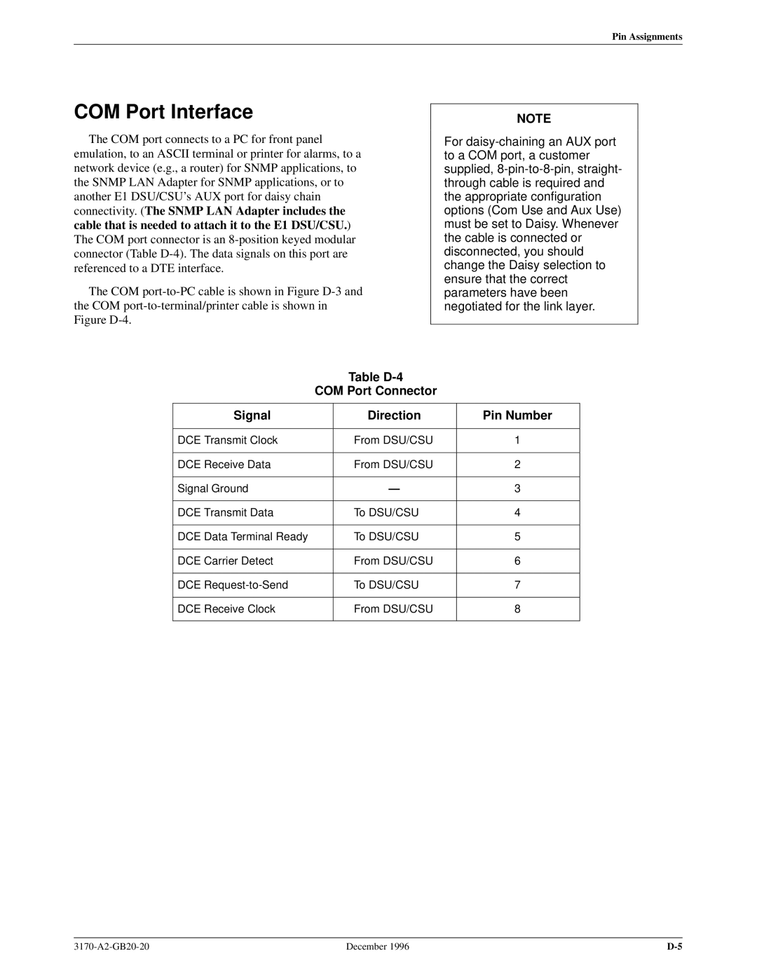
Table D-4
COM Port Connector
Signal
Direction
Pin Number
DCE Transmit Clock
From DSU/CSU
1
DCE Receive Data
From DSU/CSU
2
Signal Ground | Ð | 3 |
|
|
|
DCE Transmit Data | To DSU/CSU | 4 |
|
|
|
DCE Data Terminal Ready | To DSU/CSU | 5 |
|
|
|
DCE Carrier Detect | From DSU/CSU | 6 |
|
|
|
DCE | To DSU/CSU | 7 |
|
|
|
DCE Receive Clock | From DSU/CSU | 8 |
|
|
|
December 1996 |