ACCULINK 317x E1 DSU/CSU
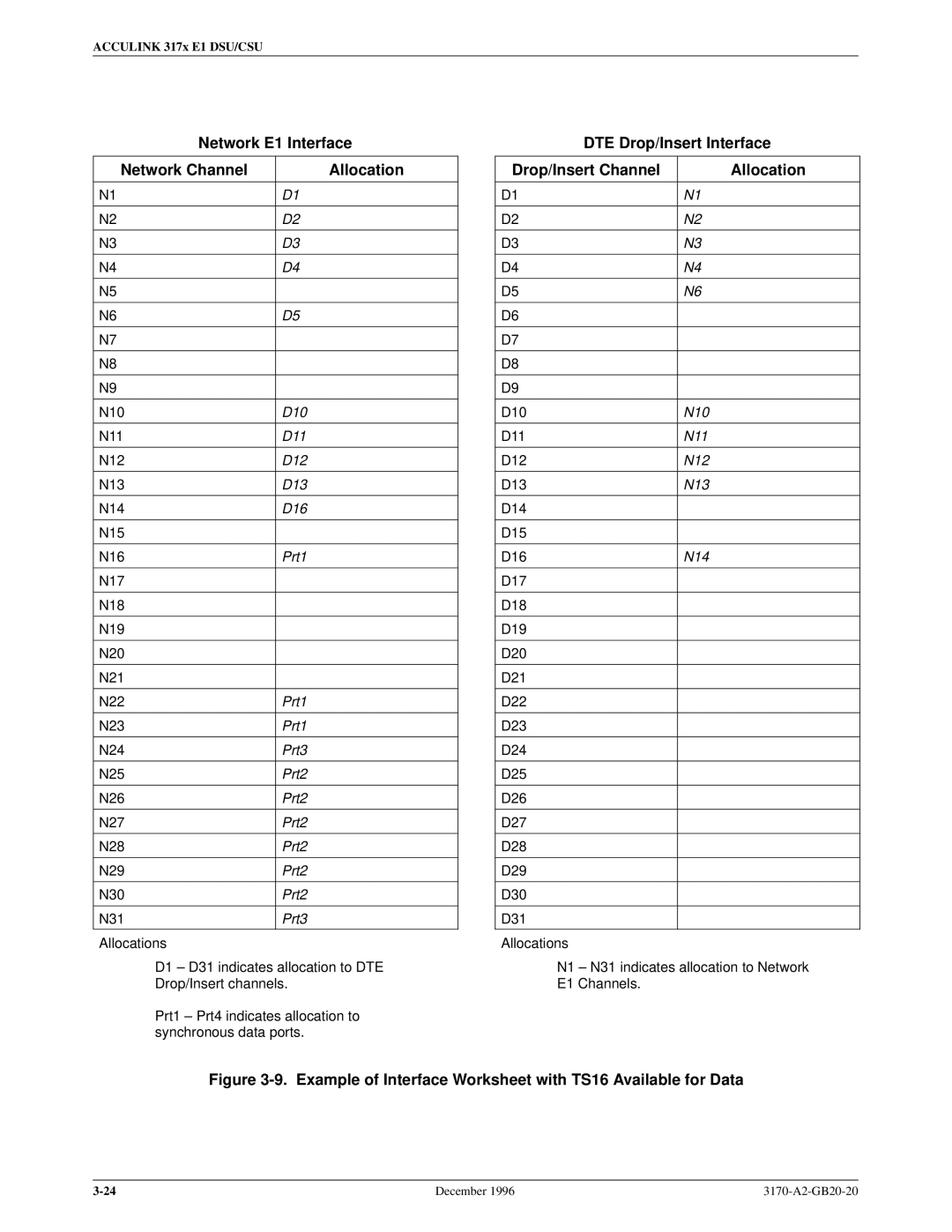
Network E1 Interface
Network Channel | Allocation |
|
|
N1 | D1 |
|
|
N2 | D2 |
|
|
N3 | D3 |
|
|
N4 | D4 |
|
|
N5 |
|
|
|
N6 | D5 |
|
|
N7 |
|
|
|
N8 |
|
|
|
N9 |
|
|
|
N10 | D10 |
|
|
N11 | D11 |
|
|
N12 | D12 |
|
|
N13 | D13 |
|
|
N14 | D16 |
|
|
N15 |
|
|
|
N16 | Prt1 |
|
|
N17 |
|
|
|
N18 |
|
|
|
N19 |
|
|
|
N20 |
|
|
|
N21 |
|
|
|
N22 | Prt1 |
|
|
N23 | Prt1 |
|
|
N24 | Prt3 |
|
|
N25 | Prt2 |
|
|
N26 | Prt2 |
|
|
N27 | Prt2 |
|
|
N28 | Prt2 |
|
|
N29 | Prt2 |
|
|
N30 | Prt2 |
|
|
N31 | Prt3 |
|
|
Allocations |
|
D1 ± D31 indicates allocation to DTE
Drop/Insert channels.
Prt1 ± Prt4 indicates allocation to synchronous data ports.
DTE Drop/Insert Interface
Drop/Insert Channel | Allocation |
|
|
D1 | N1 |
|
|
D2 | N2 |
|
|
D3 | N3 |
|
|
D4 | N4 |
|
|
D5 | N6 |
|
|
D6 |
|
|
|
D7 |
|
|
|
D8 |
|
|
|
D9 |
|
|
|
D10 | N10 |
|
|
D11 | N11 |
|
|
D12 | N12 |
|
|
D13 | N13 |
|
|
D14 |
|
|
|
D15 |
|
|
|
D16 | N14 |
|
|
D17 |
|
|
|
D18 |
|
|
|
D19 |
|
|
|
D20 |
|
|
|
D21 |
|
|
|
D22 |
|
|
|
D23 |
|
|
|
D24 |
|
|
|
D25 |
|
|
|
D26 |
|
|
|
D27 |
|
|
|
D28 |
|
|
|
D29 |
|
|
|
D30 |
|
|
|
D31 |
|
|
|
Allocations |
|
N1 ± N31 indicates allocation to Network
E1 Channels.
Figure 3-9. Example of Interface Worksheet with TS16 Available for Data
December 1996 |