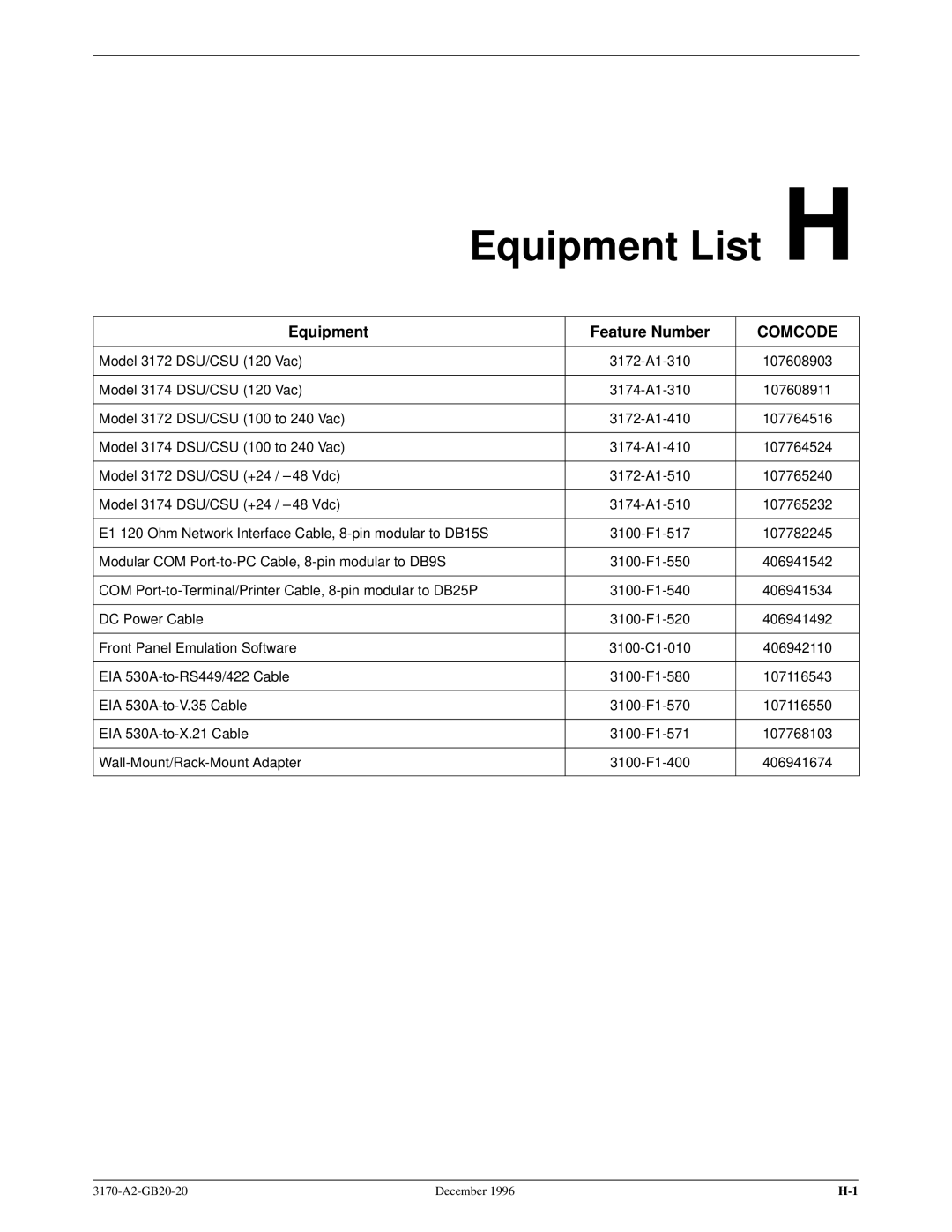
Document No. 3170-A2-GB20-20
OPERATORS GUIDE
December
CHANNEL SERVICE UNIT
Warranty, Sales, and Service Information
ACCULINK 317x E1 Data Service Unit/Channel Service Unit
Trademarks
COPYRIGHT 1996 Paradyne Corporation. All rights reserved
Important Instructions
Important Safety Instructions
Notices
Models 3172-A1-410 and 3174-A1-410 Only
CE Marking
2. Installation
Table of Contents
Preface
1. Introduction
4. Maintenance
Glossary Index
Appendices
Objectives and Reader Assumptions
Preface
Related Document
Reference Documents
Features
Introduction
Overview
DTE Drop/Insert Interface
Alarm Message Capability
Front Panel Emulation
SNMP Management Support
Rear Panel
Physical Description
Front Panel
Figure 1-1. Front Panel
Figure 1-3. Model 3174 Rear Panel
Figure 1-2. Model 3172 Rear Panel
ACCULINK 317x E1 DSU/CSU
December
Name
Rear Panel Connectors and Switches
Function
Introduction
Application Examples
Installation
NETWORK
Figure 2-1. Point-to-Point Application Example
Figure 2-2. Shared Access Application Example
SERVICES
Figure 2-4. Wireless/DACS Application Example
FRACTIONAL NETWORK
Figure 2-5. Direct Connection to an SNMP Manager
SNMP Connection Examples
Figure 2-6. Connection through a Router to SNMP
NETWORK
Figure 2-8. LAN Adapter and Daisy Chaining for SNMP Support
Figure 2-7. Connection through a LAN Adapter to SNMP
Figure 2-9. Remote SNMP Management through FDL/EDL
NETWORK
Installing the +24 Vdc Power Supply
Optional Power Sources
HANDLING PRECAUTIONS FOR STATIC-SENSITIVE DEVICES
Figure 2-10. +24 Vdc Power Supply Pinouts
Figure 2-11. ±48 Vdc Single Source Power Supply Pinouts
Installing the Single ±48 Vdc Power Supply
Figure 2-12. ±48 Vdc Redundant Source Power Supply Pinouts
Installing the Redundant ±48 Vdc Power Supply
Cabling Examples
Figure 2-13. Cabling Examples
NETWORK
Self-Test In Progress
Power-Up Self-Test
Self-Test Passed
Self-Test
Operation
Using the Front Panel
Figure 3-1. E1 DSU/CSU Front Panel
Overview
Keypad
Figure 3-2. LCD
Figure 3-3. Keypad
LEDs
Test Jacks
Figure 3-4. Test Jacks
Figure 3-5. E1 DSU/CSU LEDs
Color
System LEDs
Meaning
NETWORK Interface LEDs
Name
DTE Drop/Insert Port LEDs
Color
Meaning
Name
Data Port LEDs
Color
Meaning
Displaying Unit Identity
To change the customer identification CID
Displaying LED Conditions
Selecting the DTE Drop/Insert or Data Port for LED Display
Changing Configuration Options
Displaying/Editing Configuration Options
Selecting/Copying to a Specific Port
Saving Edit Changes
Save Edit to Activ Cust1
Port Select Copy Prt1 Prt2
Selecting the Port
Configuring the E1 DSU/CSU for SNMP Management
Alarm
Setting the IP Address
SNMP Config Gen Trap
Com Use Next SNMP ASCII
010.155.111.222 Up Down Save
Selecting the Link Layer Protocol
Com Link Next PPP SLIP
Alarm
CommunityName1 Next Edit Clear
Specifying the Community Names and Access Types
public Up Down Save
Alarm
Enabling SNMP Trap Messages
Configuring SNMP Traps
Selecting the Number of Trap Managers
Configuring a Destination for SNMP Traps
Num Trap Mgrs1
Next
Configuring DS0 Channels
3-21
Operation
Network Channel
Network E1 Interface
Allocation
DTE Drop/Insert Interface
Operation
NETWORK INTERFACE N1 N2 N3 N4 N5 N6 N7 N8 N9 N10 N11 N12 N13 N14 N15
3-23
Network Channel
Network E1 Interface
Allocation
DTE Drop/Insert Interface
Port Chan
Figure 3-10. Port Channel Configuration Worksheet Ports 1 and
Options
Value
Port Chan
Figure 3-11. Port Channel Configuration Worksheet Ports 3 and
Options
Value
Symbol
Display Channel Symbols
Displaying DS0 Channel Assignments
Meaning
Allocating Data Ports
Block Channel Assignment Method
Individual Channel Assignment Method
7. From the DTE Channels screen, press F1 to select TS16
Clearing DS0 Channel Allocation
Providing Backup Capability
Selecting the Timing Source
Figure 3-12. Common Clocking Configurations
Configuring for External Timing
Configuring for Network Timing
Edit NET Chan Gen
Pri Clk SrcNET Next NET DTE
Acquiring the Active User Interface
Acquiring/Releasing the User Interface
Releasing the Active User Interface
User I/F active
Download Operations
Resetting the E1 DSU/CSU
Changing User Interface Access Security
E1 DSU/CSU User Interface Access Security
Maintenance
Self-Test Health Messages
Self-Test Health
Message
Description
Maintenance
Device Health and Status
Message
Health and Status Messages
Description
LOS at Net
Performance NET Prt1 Prt2
Network Performance Reports
NET Registers Cur 24Tot Intvl
NET Current Event = xx,xxx
NET Intvl Up Down Dsply
Register
1 of Performance Registers
Interval Description
Totals Description
Register
2 of Performance Registers
Interval Description
Totals Description
Alarms
Enterprise-Specific Trap Definitions
SNMP Traps
Trap Value
Event
1 of Troubleshooting
Troubleshooting
Symptom
Solutions
Symptom
2 of Troubleshooting
Solutions
Possible Cause
Test Jacks
Figure 4-2. Test Jack Block Diagram
Figure 4-1. E1 DSU/CSU Test Jacks
Test Jack Functions
Remote Loopback Tests
Test Commands
Valid Loopback Combinations
Local Loopback Tests
Starting a Payload Loopback
Starting a Line Loopback
Loopback Abort LLB PLB
Test Rlpbk Lpbk Ptrns
Starting a Repeater Loopback
Starting a DTE Loopback
Rlpbk
Lpbk
Starting a Data Channel Loopback
Aborting Loopbacks
Starting a Data Terminal Loopback
Test Patterns
Sending Test Patterns
Abort Test Name
Valid Send Test Pattern Combinations
Send Name and Dest
511 Port
1-in-8 Network
Aborting Test Patterns
Monitoring Test Patterns on Individual Data Ports
Patterns Mon QRSS
Monitor Name Prt1 Prt2 Prt3
Lamp Test
Starting a Lamp Test
Abort Send or Mon
Aborting a Lamp Test
Displaying E1 DSU/CSU Test Status
Test Status Messages
Message
Description
Front Panel Menu A
Models 3172/3174 DSU/CSUs Technical Specifications
Technical Specifications B
Specifications
1 of
Models 3172/3174 DSU/CSUs Technical Specifications
2 of
Specifications
PHYSICAL DIMENSIONS
DTE Interface Configuration Options
Configuration Options C
Port Configuration Options
Network Interface Configuration Options
Table C-1 DTE Interface Configuration Options
DTE Interface Configuration Options
DTE Port Enab Next Enab Disab Prev
DTE Frame noCRC Next CRC4 noCRC Prev
Table C-2 1 of Port Configuration Options
Port Configuration Options
Port Type E530 Next E530 V.35 RS449 Prev
Base Rate Nx64 Next Nx64 Nx56 Prev
All Ones Both Next Disab DTR RTS Both Prev
Table C-2 2 of Port Configuration Options
Rcv RAI Halt Next None Halt Prev
Tx Clock Int Next Int Ext Prev
EDL Disab Next Enab Disab Prev
Table C-2 3 of Port Configuration Options
Err Rate 10E-4 Next 10E-4 10E-5 10E-6 10E-7 10E-8 10E-9 Prev
Near-end Disab Next Disab Maint Send Both Prev
Table C-2 4 of Port Configuration Options
Far-end Disab Next Disab Maint Prev
Mgmt Link Disab Next Disab SNMP Prev
Table C-3 Network Interface Configuration Options
Network Interface Configuration Options
NET Frame noCRC Next CRC4 noCRC Prev
Mgmt Link Disab Next Disab SNMP Prev
Table C-4 DTE Channel Configuration Options
Channel Configuration Options
DTE Channels TS16 Assign
TS16 Rsvd Data Rsvd
Channel Config Dsply Clear DTE Prt1 Prt2 Prt3 Prt4
Table C-5 1 of Data Port Channel Configuration Options
Assign To NET Next NET DTE Prtn Prtn Prtn Prev
Assign By Block Next Block Chan Prev
Port Rate
Table C-5 2 of Data Port Channel Configuration Options
Next
1024
Next
Table C-5 3 of Data Port Channel Configuration Options
Prev
Next
Table C-6 General Configuration Options
General Configuration Options
Pri Clk Src NET Next NET DTE Prt1 Prt2 Prt3 Prt4 Int Ext Prev
Sec Clk Src NET Next NET DTE Prt1 Prt2 Prt3 Prt4 Ext Disab Prev
Table C-7 1 of User Interface Configuration Options
User Interface Configuration Options
Self-Test Enab Next Enab Disab Prev
Com Use ASCII Next SNMP ASCII Daisy Prev
Com Rate Next 1.2 2.4 4.8 9.6 14.4 19.2 38.4 Prev
Table C-7 2 of User Interface Configuration Options
Char Length Next 7 8 Prev
CParity None Next None Even Odd Prev
Ignore DTR No Next Yes No Prev
Table C-7 3 of User Interface Configuration Options
Aux Use None Next None SNMP Daisy Prev
Aux Rate Next 9.6 14.4 19.2 38.4 Prev
Table C-8 Alarm Configuration Options
Alarm Configuration Options
Alrm Msg Disab Next Enab Disab Prev
SNMP Trap Disab Next Enab Disab Prev
Table C-9 1 of General SNMP Configuration Options
SNMP Configuration Options
Access 1 Read Next Read R/W Prev
System Name Next Edit Clear Prev
Access 2 Read Next Read R/W Prev
Table C-9 2 of General SNMP Configuration Options
CommunityName2 Next Edit Clear Prev
IP Adr Next Edit Clear Prev
Com IP Adr Next Edit Clear Prev
Table C-9 3 of General SNMP Configuration Options
Com NetMask Next Edit Clear Prev
Com Link PPP Next PPP SLIP Prev
Aux IP Adr Next Edit Clear Prev
Table C-9 4 of General SNMP Configuration Options
Aux NetMask Next Edit Clear Prev
Def Netwk None Next None Com Aux FDL EDL1 EDL2 EDL3 EDL4 Prev
Num Trap Mgrs Next 1 2 3 4 5 6 Prev
Table C-10 1 of SNMP Trap Configuration Options
Trapn IP Adr Clear Next Edit Clear Prev
Trapn Dst None Next None Com Aux FDL EDL1 EDL2 EDL3 EDL4 Prev
Entp Trap Enab Next Enab Disab Prev
Table C-10 2 of SNMP Trap Configuration Options
Link Trap Both Next Disab Up Down Both Prev
Trap I/F All Next NET DTE E1s Ports All Prev
Alarm
Configuration Worksheets
DTE Options
Net Options
Prt2 Options
Prt1 Options
Prt3 Options
Prt4 Options
Network Channel
Network E1 Interface
Allocation
DTE Drop/Insert Interface
Options
Port Chan
Value
Conf
Options
Port Chan
Value
Conf
SNMP Trap
General SNMP
Value
Options
Overview
Pin Assignments D
E1 Network Interface
Signal
Table D-1
Pin Number
Table D-2
DTE Drop/Insert Interface
Figure D-2. DTE Drop/Insert Cable
Signal
AUX Port Interface
Table D-3 AUX Port Connector
Direction
Signal
COM Port Interface
Table D-4 COM Port Connector
Signal
Direction
Figure D-4. COM Port-to-Terminal/Printer Cable
Figure D-3. COM Port-to-PC Cable
ACCULINK 317x E1 DSU/CSU
December
Table D-5 EIA 530A Port Interface DB25 Connector
EIA 530A Port Interface Connector
Circuit
CCITT
EIA 530A-to-RS449 Cable Interface
Figure D-5. EIA 530A-to-RS449 Cable
ACCULINK 317x E1 DSU/CSU
Signal
Table D-6 RS449 Cable Interface
Circuit
CCITT
Figure D-6. EIA 530A-to-V.35 Cable
EIA 530A-to-V.35 Cable Interface
ACCULINK 317x E1 DSU/CSU
D-10
Signal
Table D-7 V.35 Cable Interface
CCITT
Direction
Figure D-7. EIA 530A-to-X.21 Cable
EIA 530A-to-X.21 Cable Interface
ACCULINK 317x E1 DSU/CSU
D-12
Signal
Table D-8 X.21 Cable Interface
CCITT
Direction
Optional DC Power Cable
Power Input Connector
Table D-9 DC Power Connector
Figure D-8. DC Power Cable
Figure D-9. External Clock Connector
Table D-10 External Clock Connector
External Clock Interface
Signal
SNMP MIB Objects E
Management Information Base MIB II RFC
Overview
System Group, MIB
System Group ± ªsysServicesº Object system
System Group ± ªsysDescrº Object system
System Group ± ªsysObjectIDº Object system
Interface Group ± ªifIndexº Object ifEntry
Interface Group ± ªifDescrº Object ifEntry
Interface Group ± ªifTypeº Object ifEntry
Interface Group ± ªifMtuº Object ifEntry
Interface Group ± ªifAdminStatusº Object ifEntry
Interface Group ± ªifSpeedº Object ifEntry
Interface Group ± ªifOperStatusº Object ifEntry
Interface Group ± Input Counters objects ifEntry 10 to ifEntry
Interface Group ± ªifLastChangeº Object ifEntry
Interface Group ± Output Counters objects ifEntry 16 to ifEntry
IP Group, MIB
IP Group ± ªipRouteDestº Object ipRouteEntry
IP Group ± ªipRouteTableº Object ip
IP Group ± ªipRouteIfIndexº Object ipRouteEntry
IP Group ± ªipRouteMetric2º Object ipRouteEntry
Transmission Group, MIB
IP Group ± ªipRouteProtoº Object ipRouteEntry
IP Group ± ªipRouteAgeº Object ipRouteEntry
ICMP Group, MIB
Near End Group ± ªdsx1ValidIntervalsº Object dsx1ConfigEntry
Near End Group ± ªdsx1TimeElapsedº Object dsx1ConfigEntry
Near End Group ± ªdsx1LineTypeº Object dsx1ConfigEntry
Near End Group ± ªdsx1LineCodingº Object dsx1ConfigEntry
Near End Group ± ªdsx1LoopbackConfigº Object dsx1ConfigEntry
Near End Group ± ªdsx1CircuitIdentifierº Object dsx1ConfigEntry
Near End Group ± ªdsx1LineStatusº Object dsx1ConfigEntry
Near End Group ± ªdsx1SignalModeº Object dsx1ConfigEntry
Near End Group ± The DS1 Current Table Objects dsx1CurrentEntry
Near End Group ± ªdsx1Fdlº Object dsx1ConfigEntry
Near End Group ± The DS1 Interval Table Objects dsx1IntervalEntry
Near End Group ± The DS1 Total Table Objects dsx1TotalEntry
The DS1 Fractional Group, DS1/E1 MIB
RS-232-like MIB RFC
Number of Ports ± ªrs232Numberº Object rs232
General Port Table, RS-232-like MIB
General Port Table ± ªrs232PortOutSpeedº Object rs232PortEntry
General Port Table ± ªrs232PortTypeº Object rs232PortEntry
General Port Table ± ªrs232PortInSigNumberº Object rs232PortEntry
General Port Table ± ªrs232PortOutSigNumberº Object rs232PortEntry
Input Signal Table ± ªrs232InSigStateº rs232InSigEntry
Input Signal Table ± ªrs232InSigNameº rs232InSigEntry
Input Signal Table ± ªrs232InSigChangesº rs232InSigEntry
Output Signal Table, RS-232-like MIB
Output Signal Table ± ªrs232OutSigChangesº rs232OutSigEntry
Generic-Interface Extension MIB RFC
Generic Interface Test Table, Generic Interface MIB
E-15
Paradyne Enterprise MIB
Table E-1 1 of SNMP MIB to Front Panel Command Cross-Reference
Correlation between Menu Commands and SNMP Objects
Front Panel Command
SNMP MIB Object
Front Panel Command
Table E-1 2 of SNMP MIB to Front Panel Command Cross-Reference
Set dsx1LoopbackConfig for Net E1 to dsx1LineLoop
Set dsx1LoopbackConfig for Net E1 to dsx1NoLoop
Front Panel Command
Table E-1 3 of SNMP MIB to Front Panel Command Cross-Reference
SNMP MIB Object
external
IP Network Addressing Scenario F
IP Network Addressing
Overview
135.18.1.4
135.18.1.2
Figure F-1. Daisy-Chained Standalone Devices at the Central Site
NETWORK
Front Panel Emulation G
Installing Front Panel Emulation Software
Overview
6. PRESS ENTER
Starting Front Panel Emulation
Equipment List H
Feature Number
Equipment
COMCODE
Glossary
block allocation method
CRC6
DS0 channel allocation
frame relay
Lpbk branch
power-up self-test
self-test
warmStart trap
wireless communications
XTXC
1in8 Test
Index
Page
Page