Channel Service Unit
Copyright � 1996 Paradyne Corporation. All rights reserved
Warranty, Sales, and Service Information
Trademarks
Operators Guide 3170-A2-GB20-20
Important Safety Instructions
Acculink 317x E1 DSU/CSU
Models 3172-A1-410 and 3174-A1-410 Only
CE Marking
Table of Contents
Glossary Index
Reference Documents
Preface
Objectives and Reader Assumptions
Related Document
Introduction
Features
Overview
Snmp Management Support
Alarm Message Capability
DTE Drop/Insert Interface
Front Panel Emulation
Rear Panel
Physical Description
Front Panel
Model 3172 Rear Panel
Name Function
Rear Panel Connectors and Switches
Application Examples
Installation
Services
Direct Connection to an Snmp Manager
Snmp Connection Examples
Connection through a LAN Adapter to Snmp
Installing the +24 Vdc Power Supply
Optional Power Sources
Important Instructions
11. ±48 Vdc Single Source Power Supply Pinouts
Installing the Single ±48 Vdc Power Supply
12. ±48 Vdc Redundant Source Power Supply Pinouts
Installing the Redundant ±48 Vdc Power Supply
13. Cabling Examples
Cabling Examples
Self-Test
Power-Up Self-Test
Self-Test Progress
Self-Test Passed
Operation
E1 DSU/CSU Front Panel
Using the Front Panel
LCD
Keypad
LEDs
Test Jacks
Name Color Meaning
System LEDs
Network Interface LEDs
PDV
DTE Drop/Insert Port LEDs
DTR
Data Port LEDs
Displaying Unit Identity
ClrReg
Control Reset CID DL
Test Cnfig Ctrl
Control Rel
LED Display Test NetSig
Displaying LED Conditions
Status Perf TStat LED
Select LEDs E1 Prt1 Prt2
Prt1 Prt2
Changing Configuration Options
Selecting the DTE Drop/Insert or Data Port for LED Display
LED Dsply DTE
Edit DTE Port NET
Displaying/Editing Configuration Options
Load from Activ Cust1
Choose Funct Edit Save
Port Select Copy Prt1 Prt2
Saving Edit Changes
Selecting/Copying to a Specific Port
Save Edit to Activ Cust1
Selecting the Port
Configuring the E1 DSU/CSU for Snmp Management
Setting the IP Address
010.155.111.222 Up Down Save
Selecting the Link Layer Protocol
Com Link Next PPP Slip
CommunityName1 Next Edit Clear
Specifying the Community Names and Access Types
Public Up Down Save
Snmp Trap Next Enab Disab
Configuring Snmp Traps
Access Next Read R/W
Enabling Snmp Trap Messages
Trapn Dst Next None Com
Configuring a Destination for Snmp Traps
Selecting the Number of Trap Managers
Num Trap Mgrs1 Next
Configuring DS0 Channels
DROP/INSERT Interface Network Interface
DTE Drop/Insert Interface Drop/Insert Channel Allocation
Network E1 Interface Network Channel Allocation
Example of Channel Allocation with TS16 Available for Data
Example of Interface Worksheet with TS16 Available for Data
Port Chan Options Value Conf
10. Port Channel Configuration Worksheet Ports 1
11. Port Channel Configuration Worksheet Ports 3
Symbol Meaning
Display Channel Symbols
Displaying DS0 Channel Assignments
Chan
Allocating Data Ports
Prt1
EditDTE Port
Block Channel Assignment Method
Individual Channel Assignment Method
TS16Rsvd Data Rsvd
DTE Channels TS16 Assign
Port1
Providing Backup Capability
Clearing DS0 Channel Allocation
Clear Channel
Selecting the Timing Source
12. Common Clocking Configurations
Pri Clk SrcNET Next NET DTE
Configuring for Network Timing
Configuring for External Timing
Edit NET Chan Gen
Clock Rate2048 Next 2048
Acquiring/Releasing User Interface
Acquiring the Active User Interface
Releasing the Active User Interface
Download Operations
Resetting the E1 DSU/CSU
Control ClrReg Reset
Device Reset Yes No
Changing User Interface Access Security
E1 DSU/CSU User Interface Access Security
Security Lvl1 Lvl2
Maintenance
Message Description
Self-Test Health
SelfTst Health Passed
Self-Test Health Messages
Device H/S OOF at DTE
Device Health and Status
Auto Dev H/S OOF at DTE
Health and Status Messages
NET Current Event = xx,xxx
Network Performance Reports
Performance NET Prt1 Prt2
NET Registers Cur 24Tot Intvl
Clear Prf Regs NET Prt1 Prt2
Clear NETRegs Command Complete
NET Intvl Up Down Dsply
NET Intvl nn ES=xxx
Event
CurTimer
VldIntvl
Complete
StEvnt
Alarms
Enterprise-Specific Trap Definitions Trap Value Event
Snmp Traps
Snmp Trap per Interface Trap Meaning
RAI at DTE
Troubleshooting
Troubleshooting Symptom Possible Cause Solutions
RAI at Net
# # # # # # # #
AIS at DTE
Test Jacks
Rem Loopback
Test Commands
Remote Loopback Tests
Test Rlpbk Lpbk Ptrns
Valid Loopback Combinations
Local Loopback Tests
Starting a Payload Loopback
Starting a Line Loopback
Loopback Abort LLB PLB
Starting a Repeater Loopback
Starting a DTE Loopback
Loopback
Loopback Dclb Prt1 Prt2 Prt3
Starting a Data Channel Loopback
Aborting Loopbacks
Starting a Data Terminal Loopback
Loopback Dtlb Prt1 Prt2 Prt3
Patterns Abort Send Mon
Test Patterns
Sending Test Patterns
Loopback Abort All
8 Network Qrss Port
Patterns Send 511 1in8 Qrss
Test Started
Send Name Prt1 Prt2 Prt3
Monitor Name Prt1 Prt2 Prt3
Monitoring Test Patterns on Individual Data Ports
Aborting Test Patterns
Patterns Mon Qrss
Test Lpbk Ptrns Lamp
Lamp Test
Starting a Lamp Test
Patterns Abort All Send Mon
Status STest Perf TStat
Displaying E1 DSU/CSU Test Status
Aborting a Lamp Test
0123456789 = ?
Message Description
Test Status Messages
CID
Front Panel Menu a
Table B-1
Technical Specifications B
Models 3172/3174 DSU/CSUs Technical Specifications
Specifications Criteria
Port Interface
DTE Interface Configuration Options
Configuration Options C
Table C-1 DTE Interface Configuration Options
DTE Interface Configuration Options
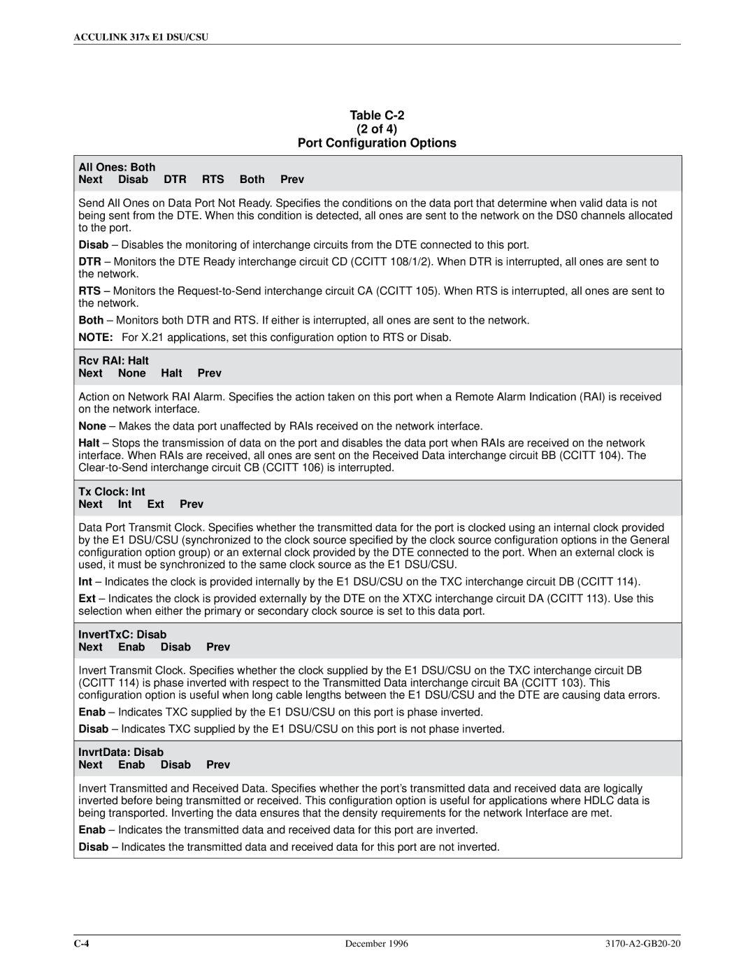
Table C-2 Port Configuration Options
Port Configuration Options
InvertTxC Disab Next Enab Disab Prev
All Ones Both Next Disab DTR RTS Both Prev
Rcv RAI Halt Next None Halt Prev
Tx Clock Int Next Int Ext Prev
Near-end Disab Next Disab Maint Send Both Prev
EDL Disab Next Enab Disab Prev
Mgmt Link Disab Next Disab Snmp Prev
Far-end Disab Next Disab Maint Prev
Circuit Ident Next Edit Clear Prev
Network Interface Configuration Options
Table C-3 Network Interface Configuration Options
NET Frame noCRC Next CRC4 noCRC Prev
Table C-4 DTE Channel Configuration Options
Channel Configuration Options
Assign By Block Next Block Chan Prev
Table C-5 Data Port Channel Configuration Options
Channel Config Dsply Clear DTE Prt1 Prt2 Prt3 Prt4
Assign To NET Next NET DTE Prtn Prtn Prtn Prev
1472 1536 1600
Port Rate Next 128 192 256 320 384 448 512 576 640 704
832 896 960 1024 1088
1216 1280 1344
N10 N11 N12 N31 Next Prev D10 D11 D12 D31
Table C-6 General Configuration Options
General Configuration Options
Clock Rate Next 2048 8 Prev
Table C-7 User Interface Configuration Options
User Interface Configuration Options
CStop Bits Next 1 1.5 2 Prev
Com Rate Next 1.2 2.4 4.8 9.6 14.4 19.2 38.4 Prev
Char Length Next 7 8 Prev
CParity None Next None Even Odd Prev
Aux Use None Next None Snmp Daisy Prev
Ignore DTR No Next Yes No Prev
Aux Rate Next 9.6 14.4 19.2 38.4 Prev
Snmp Trap Disab Next Enab Disab Prev
Alarm Configuration Options
Table C-8 Alarm Configuration Options
Alrm Msg Disab Next Enab Disab Prev
Table C-9 General Snmp Configuration Options
Snmp Configuration Options
NetMask Next Edit Clear Prev
Access 2 Read Next Read R/W Prev
CommunityName2 Next Edit Clear Prev
IP Adr Next Edit Clear Prev
Com NetMask Next Edit Clear Prev
Com IP Adr Next Edit Clear Prev
Com Link PPP Next PPP Slip Prev
Aux NetMask Next Edit Clear Prev
Aux IP Adr Next Edit Clear Prev
Gen Trap Both Next Disab Warm Auth Both Prev
Table C-10 Snmp Trap Configuration Options
Num Trap Mgrs Next 1 2 3 4 5 6 Prev
Trapn IP Adr Clear Next Edit Clear Prev
Link Trap Both Next Disab Up Down Both Prev
Entp Trap Enab Next Enab Disab Prev
Trap I/F All Next NET DTE E1s Ports All Prev
Configuration Worksheets
Prt4 Options Value
Prt1 Options Value
Prt2 Options Value
Prt3 Options Value
Network E1 Interface Network Channel Allocation
Port Chan Options Value Conf
Port Chan Options Value Conf
Snmp Trap Value Options
General Snmp Value Options
Pin Assignments D
Table D-1
Signal Pin Number
E1 120 Ohm Balanced Interface Connector
E1 Network Interface
DTE Drop/Insert Interface
DTE Drop/Insert Connector
Table D-2
AUX Port Interface
Table D-3 AUX Port Connector Signal Direction Pin Number
COM Port Interface
Table D-4 COM Port Connector Signal Direction Pin Number
Figure D-3. COM Port-to-PC Cable
Direction Pin Mnemonic Number
EIA 530A Port Interface Connector
Figure D-5. EIA 530A-to-RS449 Cable
EIA 530A-to-RS449 Cable Interface
Table D-6 RS449 Cable Interface Signal Circuit
Figure D-6. EIA 530A-to-V.35 Cable
EIA 530A-to-V.35 Cable Interface
Direction Pin Number
Table D-7 Cable Interface Signal
Figure D-7. EIA 530A-to-X.21 Cable
EIA 530A-to-X.21 Cable Interface
Table D-8 Cable Interface Signal
Optional DC Power Cable
Power Input Connector
Table D-9 DC Power Connector Signal Pin Number
External Clock Interface
Table D-10 External Clock Connector Signal Pin Number
Management Information Base MIB II RFC
Snmp MIB Objects E
Interface Group, MIB
System Group, MIB
Interface Group ± ªifDescrº Object ifEntry
Interface Group ± ªifIndexº Object ifEntry
Interface Group ± ªifTypeº Object ifEntry
Interface Group ± ªifOperStatusº Object ifEntry
Interface Group ± ªifAdminStatusº Object ifEntry
Interface Group ± ªifMtuº Object ifEntry
Interface Group ± ªifSpeedº Object ifEntry
IP Group, MIB
IP Group ± ªipRouteMetric2º Object ipRouteEntry
IP Group ± ªipRouteTableº Object ip
IP Group ± ªipRouteDestº Object ipRouteEntry
IP Group ± ªipRouteIfIndexº Object ipRouteEntry
Snmp Group, MIB
Transmission Group, MIB
Icmp Group, MIB
UDP Group, MIB
Near End Group, DS1/E1 MIB
DS1/E1 MIB RFC
Near End Group ± ªdsx1SignalModeº Object dsx1ConfigEntry
Near End Group ± ªdsx1LineStatusº Object dsx1ConfigEntry
Near End Group ± The DS1 Total Table Objects dsx1TotalEntry
Near End Group ± ªdsx1Fdlº Object dsx1ConfigEntry
Far End Group, DS1/E1 MIB
General Port Table, RS-232-like MIB
RS-232-like MIB RFC
DS1 Fractional Group, DS1/E1 MIB
Number of Ports ± ªrs232Numberº Object rs232
Asynchronous Port Table, RS-232-like MIB
General Port Table ± ªrs232PortTypeº Object rs232PortEntry
Input Signal Table, RS-232-like MIB
Output Signal Table, RS-232-like MIB
Synchronous Port Table, RS-232-like MIB
Generic-Interface Extension MIB RFC
Output Signal Table ± ªrs232OutSigChangesº rs232OutSigEntry
Generic Interface Test Table, Generic Interface MIB
Paradyne Enterprise MIB
Correlation between Menu Commands and Snmp Objects
Set dsx1LoopbackConfig for DTE E1 to dsx1LineLoop
Set dsx1LoopbackConfig for Net E1 to dsx1LineLoop
Set dsx1LoopbackConfig for Net E1 to dsx1NoLoop
Set dsx1LoopbackConfig for Net E1 to dsx1PayloadLoop
Set/Display dsx1FracNumber and dsx1Fracifindex for DTE or
Set/Display dsx1FracNumber and dsx1FracIfindex for DTE E1
Display rs232PortInSpeed or rs232PortOutSpeed for port n
IP Network Addressing
IP Network Addressing Scenario F
135.18.1.2
Front Panel Emulation G
Installing Front Panel Emulation Software
Starting Front Panel Emulation
Equipment List H
Equipment Feature Number
Activ
Glossary
CRC4
CRC6
DTR
ISO
PDU
PPP
Slip
Xtxc
Index
Index-2
Index-3
Index-4
Index-5