User’s Manual
Page
User’s Manual
Software License Agreement
Definitions
Limited Software Product Warranty
Government Restricted Rights
Trademark Acknowledgments
Page
Table Of Contents
Configuring The Printer
Table of Contents
Approaches To Network Printing
TCP/IP Configuration
Unix Configuration
Interfaces
Extra Features
Standard Ascii Character Set
Introduction
About This Manual
Printing Conventions Used In This Manual
Damage the equipment
Example ping ipname Example ipname is alive
Related Documents
About This Manual
Printer Overview
Printronix P5000LJ Series Printer Family
Printer Overview
P5000LJ Printers
Standard Features
Taking Care Of Your Printer
Host Computer Interfaces
Printer Emulations
Graphics and Vertical Formatting
Built-in Diagnostic Tools
Output Control
Graphics Options
Graphics Options
Protocols And Emulations
Line Matrix Printing
Dot Matrix Character Formation
Printing Speed
Printing Speed
Network Interface Card NIC
What Special Features Are Available?
Network Interface Card NIC
Indication Description
Run and Auto Reset Modes
Indicator Modes
Network Indicator
Dipswitches
Dipswitch Functions
Dipswitch Comments
Downloading In a Nutshell
Downloading Function Code In P5000LJ Series Printers
Introduction
Preparation For Downloading
Introduction
Copying Function Code To Your Computer
Leave the file as it is. Do not try to execute the file
Loading Function Code To Flash Memory In The Printer
Installing Printer Emulations
Loading Function Code To Flash Memory In The Printer
Downloading Software Through the Serial or Parallel Port
Downloading Software Through the Serial or Parallel Port
Installing Printer Emulations
Navigating to the Appropriate Emulation File on the CD
This is the file you will download into the printer
Copying the Emulation File to the Download Directory
Interrupting a download will damage the flash memory on
Controller board and the NIC
Downloading Software Through Network Interface Card NIC
Downloading Software Through the Network Interface Card NIC
This is the file you will download into the NIC
Ftp xxx.xxx.xxx.xxxEnter
Downloading Optional Font Files to Flash Memory
Downloading Optional Font Files to Flash Memory
Copy /b filename.dwn LPT1Enter
Copy /b filename.dwn LPT2Enter
Clearing Program
More Flash
Loading Program Into
Overview
Configuring The Printer
Configuring The Printer
Configuring The Printer
Control Panels
Configuration Menu Overview
Locking And Unlocking The Enter Key
Configurations
Operating Modes
Changing And Saving Parameter Settings
Changing And Saving Parameter Settings
Factory Default Configuration Values
Bi-Tronics Parallel Interface
Factory Default Configuration Values
Diagnostics
NIC Interface
Hhhhhhhhhhhh
Parameter Change Example Procedure Step Key Result
Changing Parameters
Example
Changing Parameters
Example Parameter Change Example Procedure Step Key Result
To USE the Current Configuration Without Saving
Saving Your New Configuration
Config Control
Press until the desired number 1-8 displays
Printing The Current Configuration
Press until the desired option displays
Loading Configuration Values
Configuration must be saved first in order to load it
Press until the desired number
Power-Up Configuration
Allows you to make configuration
Deleting Configurations
Deleting Configurations Step Key Result
Protecting Your Configurations
Configuring NIC
Connecting To The Network
Configuration Setup
Connecting To The Network
Configuration Using The Printer Control Panel
Configuring NIC
Configuration Alternatives
Printronix Printer Manager PPM
Telnet
Telnet
Rsh spike list prn
Configuration Using a Web Browser
Remote Shell
WWW Printer Status Screen
Configuring NIC
Configuration Menus
Configuration Main Menu
Configuration Main Menu
To view options, press
Configuration Main Menu
Config. Control Menu
Load Config
Save Config
Print Config
Delete Config
Power-Up Config
Active Emulation Menu
Emulation Menu
PCL-II Emulation
LP Plus Emulations
Optional Emulations
PCL-II Emulation
PCL-II Emulation
Primary Char. Set
Secondary Char. Set
Face, CPI Delay
Length Rep
Max. Line Width
Graphics Density Perforation Skip
LPI Adjust
Config. Print
PTX Linefeed
L. /Lines
Symbol Set Print
Reset Cmd CFG Ld
LP Plus Emulation
CPI/LPI
Printer Protocol
Print Char. Set
CPI/LPI Select
Font Attributes
Format
Italic Print
Reset Cmd CFG Ld
Series Emulation
Printer Protocol
Control Code
Define CR Code
Auto LF
Overstrike
Sfcc d Command
Select Sfcc
Evfu Select
Alt. Set 80-9F
Proprinter XL Emulation
Proprinter XL Emulation
CPI Condensed
FF Valid at TOF
Alt. Char Set
Epson FX Emulation
Epson FX Emulation
Printer Select
Serial Matrix Emulation
Serial Matrix Emulation
ESC d Command
Serial Matrix Character Set Menu
Ascii USA* Ebcdic
Series XQ Emulation
Compressed Print
Elong/Alt. Font
HS Print
Upr. Case Select
IGP/PGL Emulation
Slew Relative
Define CR Code Carriage Return
Define LF Code Line Feed
Autowrap
PI Slew Range
Power on IGP/PGL
Select Font
Select LPI
Auto Uppercase
Ext Execute Copy
UPC Descenders
Compressed CPI
Ignore Char
Optimized Ratio
Error Report
IGP100 Compatbl
IGP/VGL Code V Emulation
IGP/VGL Code V Emulation
Sfcc & Pwrup
Graphics Options
Graphics Options
Free Format
Truncate Alpha
Error Handling
Midline PY includes PN
Ignore / DB8 Setup
Offpage Errors
ISO Char Set
PI Control
Hex Dump Mode
Power-up State
Maint/Misc Menu
Display Language
Power Stacker
Host Interface Menu
Host Interface Menu
Prime Signal
Bi-Tronics Submenu
Centronics Parallel Submenu
TOF Action
Buffer Size in K
Centronics Parallel Submenu
Data Bit
PI Ignored
Data Polarity
Resp. Polarity
Serial Submenu
Serial Submenu
Baud Rate
Interface Type
Data Protocol
Word Length
Stop Bits
Parity
Data Term Ready
Ethernet Submenu
Auto Switching Submenu
Auto Switching
Auto Switching Submenu
Port Type
Report Status
Timeout
Trickle Time
Ethernet Params Menu
IP Address
NetBIOS Protocol
Gateway Address
Subnet Mask
MAC Address
Printer Control Menu
Ethernet Speed
PMD Paper Motion Detection Fault
Unidirectional
Open Platen @ BOF Bottom of Form
Slow Paper Slew
Diagnostics Menu
Power Saver Time
Diagnostics Menu
Printer Tests
Test Width
Paper Out Dots
System Memory
For use with 80-column or 8.5-inch wide paper, damage to
RibbonMinder
RibbonMinder
Print Statistics
RibbonMinder Menu
New Ribbon
Ribbon Action
RibbonMinder Menu
RibbonMinder
Ribbon Type
Ribbon End Point
New Rib. Detect
Approaches To Network Printing
Peer To Peer Networks
Print Job Servers
Logical Printer Architecture
Destinations/Queues
Logical Printer Architecture
Models
Embedded NIC Web
Configuration
Configuration
Configuration Network
TCP/IP Network
Interface
Routing
Windows Network NetBIOS TCP/IP
Novell Network
Configuration Print Path
Destination Settings
Current Model Settings
Current Log Path Settings
Current Log Path Settings
Log Path Type
Log Path Port
Configuration Log Path
Logpath Type
Parallel Port PRN
Parallel Port PRN
Logpath Port
Snmp Manager Alert Posting Settings
Syslog Alert Posting Settings
Mail Alert Posting Settings
Configuration Snmp
Default Disabled
Alert Groups
Configuration Snmp Alert Groups and Printer Events
Parallel Port PRN Alert Groups and Printer Events
Passwords
System Information
Configuration System
Passwords
Status Network
Before You Begin
TCP/IP Configuration
TCP/IP NIC Configuration
Make the names easy to remember but descriptively useful
TCP/IP NIC Configuration
Creating Aliases
Methods For Setting TCP/IP Values
Methods For Setting TCP/IP Values
Method 1 Using the Printer Control Panel
Assign TCP/IP Values
Method 2 Setting TCP/IP Values Using a Network
Store TCP/IP add default router gatewayvalue
Telnet
Using Bootp
Using Bootp
TCP/IP NIC Configuration
Log in as MANAGER.SYS Enter the command run sysgen.pub.sys
HP e3000/NIC Configuration
HP e3000 / MPE-XL / MPE / iX Host Configuration
HP e3000 / MPE-XL / MPE / iX Host Configuration
Example telnet 192.192.192.192 or telnet LJ50001
Snmpenabled = false jamrecovery = false datatimeout =
Set dest d1prn backchannel prn save
NIC Configuration Verification
NIC Configuration Verification
Npconfig.pub.sys Listing Comments
Method
Methods Of Adjusting Paper Position
Methods Of Adjusting Paper Position
Using Page Level Recovery On P5000LJ Printers
Spooler 6suspendoffset=7
Restarting at a user-specified page number in a command
Using Page Level Recovery On P5000LJ Printers
MPE-XL / MPE / iX Typical Configuration
HP e3000 / MPE-XL / MPE / iX DTC Configuration
MPE-XL / MPE / iX Typical Configuration
HP e3000 / MPE-XL / MPE / iX DTC Configuration
Windows Configuration
Windows Environment Description
Windows NIC Configuration
Windows NIC Configuration
Mandatory
Optional
Communicating Across Routers
Changing Workgroup Names
Http//192.75.11.9/networkConf.html
Communicating Across Routers
Changing Destination Names
Http//192.75.11.9/destConf.html
Windows NT 3.51 Host Setup
Windows Host Configuration
Windows NT 3.51 Host Setup
Windows NT 4.0 Host Setup
Windows Host Configuration
Windows NT 4.0 Host Setup
Windows Host Configuration
Windows NT 4.0 Host Setup
Printronix P5000LJ
Windows NT 4.0 Host Setup
Windows 95/98/ME Host Setup
Windows 3.1 Host Setup
Windows Troubleshooting Tips
Windows 3.1 Host Setup
Html Configuration Forms Will Not Display
Errors Occur When Defining An LPR Printer
Windows Troubleshooting Tips
NIC Cannot Be Found On The Network
Printer Errors When Printing Or No Output
TCP/IP Access Problem
Cannot Browse The NIC On The Network
Cannot Browse The NIC On The Network
Save reset
Config http on
Web Browser/HTTP Problem
Windows NT 4.0 or 2000 Host Setup Problems
Installing Microsoft TCP/IP Printing
Web Browser/HTTP Problem
Windows Troubleshooting Tips
Unix Configuration
Unix Environment Description
Unix Environment Description
Unix NIC Configuration
Mandatory
Unix Host Configuration
Unix Host Configuration
Printing Setup On HP-UX
Drivers Required Interface
Printing Setup On HP-UX
Lp -d Quality /etc/inetd.conf
Printing Setup On Sys
HP-UX Configuration Guidelines
Example 1 Using the dest d1prn Sun
Example 2 Using the dest d1prn Sun 2.6, 2.7 and Similar
1000Q Shpw#80mx#0\ Rm=spike\ Rp=d1prn\ Lp=\
Touch /usr/spool/lpd/ 1000Q
FTP Printing
Remote Shell Printing
Nothing Prints
Unix Troubleshooting Tips
Unix Troubleshooting Tips
Stair-stepped Output
No Form Feed Or Extra Page Comes Out
204
Novell Configuration
Novell NIC Configuration
Novell Environment Description
Mandatory
Novell Environment Description
Optional
Using Html Forms
Using Html Forms
Novell Host Configuration
Novell Host Configuration
NetWare Version 3.x Pserver Setup
NetWare Version 3.x Pserver Setup
NetWare Version 3.x Rprinter Setup
NetworkConf.html e.g., http//192.75.11.9
Enter Pconsole
NetWare Version 4.x and 5.x Pserver Setup
NetWare Version 4.x and 5.x Pserver Setup
Npsh unitname command
Npsh nvplist
NetWare Version 4.x and 5.x Rprinter Setup
NetWare Version 4.x and 5.x Rprinter Setup
Chapter
NetWare 3.x No Pserver Connection
Novell Troubleshooting Tips
NetWare 3.x No Pserver Connection
Novell Troubleshooting Tips
NetWare 4.x and 5.x No Pserver Connection
Novell Configuration For 10/100Base-T Interfaces
Novell NIC Configuration 10/100Base-T
Novell NIC Configuration 10/100Base-T
Preferred File Server NDS & Bindery
Preferred File Server NDS & Bindery
Adding Preferred File Server
Store pserver novell fserver add fservername
Removing Preferred File Server
Store pserver novell fserver del fservername
Setting Password Security NDS & Bindery
Print Server Setup Html Method
Setting Password Security NDS & Bindery
Netware 4.x
Store pserver novell passwd password
Adjusting Polling Time NDS & Bindery
Print Server Setup Manual Telnet Method
Changing The Print Server Name NDS & Bindery
Changing The Print Server Name NDS & Bindery
Store pserver name name
Html Method
Manual Telnet Method
Changing The Frame Type NDS & Bindery
Changing The Frame Type NDS & Bindery
Changing The Print Server Mode NDS & Bindery
Store pserver novell mode nds bindery auto
Store pserver novell context context
Setting The NIC Context NDS
Setting The NIC Context NDS
Store pserver novell tree tree
Setting The Print Server Preferred NDS Tree NDS
Reset
NDS Pserver Setup Netware 4.x
Novell Host Configuration 10/100Base-T
NDS Pserver Setup Netware 4.x
Novell Host Configuration 10/100Base-T
Referencing a Bindery Queue In NDS Netware 3.x, 4.x,
Bindery Pserver Setup Netware 3.x, 4.x,
Bindery Pserver Setup Netware 3.x, 4.x,
RPRINTER/NPRINTER Setup Netware 3.x, 4.x,
Load pserver .salesps.sales.hp
RPRINTER/NPRINTER Setup Netware 3.x, 4.x,
Overview
Npds Configuration Netware 4.11 and Above
Npds Configuration Netware 4.11 and Above
Setup Using Rprinter Mode
Setup using Forward Jobs to a Queue Mode
Setup using LPR Mode
Troubleshooting 10/100Base-T
Pserver Setup
Troubleshooting 10/100Base-T
Http//192.168.11.9/networkNovellStatus.html
Pserver Setup
Troubleshooting 10/100Base-T
RPRINTER/NPRINTER Setup
RPRINTER/NPRINTER Setup
Printing Related
Job goes to the queue but nothing prints
Job prints incorrectly
Printing Related
242
Commands
Command Shell Overview
Access Methods
Main Command Shell Prefixes
Complete Command List
Store Commands
Command Prefixes
Store ifc from default
Store pserver from default
Store Commands
Store pserver from current
Store tcpip ifnum addr IPaddress Store tcpip 1 addr
Store tcpip tcp access root adddel IPaddress
Store tcpip ifnum mask netmask Store tcpip 1 mask
Store tcpip route del net 192.75.12.9
Store tcpip tcp rxwin packets
Set Commands
Set dest from default
Set dest from stored
Using the set sysinfo email
Set logpath from default
Set logpath from stored
Set model model name newname Set model m1 name landscape
Set model from default
Set prn timeout minutes none Set prn timeout none
Set prn from default
Set model m7 trailer $FF
Set sysinfo name newname Set sysinfo name salesprinter
Set user passwd snmp snmppassword
Set snmp
Set sysinfo module -novell -netbios
Set sysinfo logport nullsyslog
Set sysinfo email joe@192.75.11.5
Set sysinfo syslog hostIPaddress
Set user from default
Set var from default
Set user adddel username
Set user add eng
List Commands
Debug Commands
Miscellaneous Commands
Disable prn
Enable prn
Start foxttsloopb prn Start fox prn
Stop prn
Ioport
Keycode
NIC Security
Extra Features
Users And Passwords
Http//P5000LJIPaddress/adminConf.html
Http//192.75.11.9/adminConf.html
Web Browser
NIC Security
TCP Access Lists
TCP Access Lists
Printer Monitoring And Logging
Printer And Print Job Monitoring
Printer Monitoring And Logging
Key Printer Logging Terms
Printer Logging Through Logpaths
Printer Logging Through Logpaths
NIC Naming Schemes
NIC Naming Schemes
Interfaces
Centronics Parallel Interface
Centronics Parallel Interface
Centronics Interface Signals
Centronics Interface Signals
Centronics Parallel Interface Configuration
Compatibility Mode
Nibble Mode
Byte Mode
Bi-Tronics Parallel Interface
Negotiation Phase
Negotiation Phase
Signals
Not exceed 10 meters 32 feet
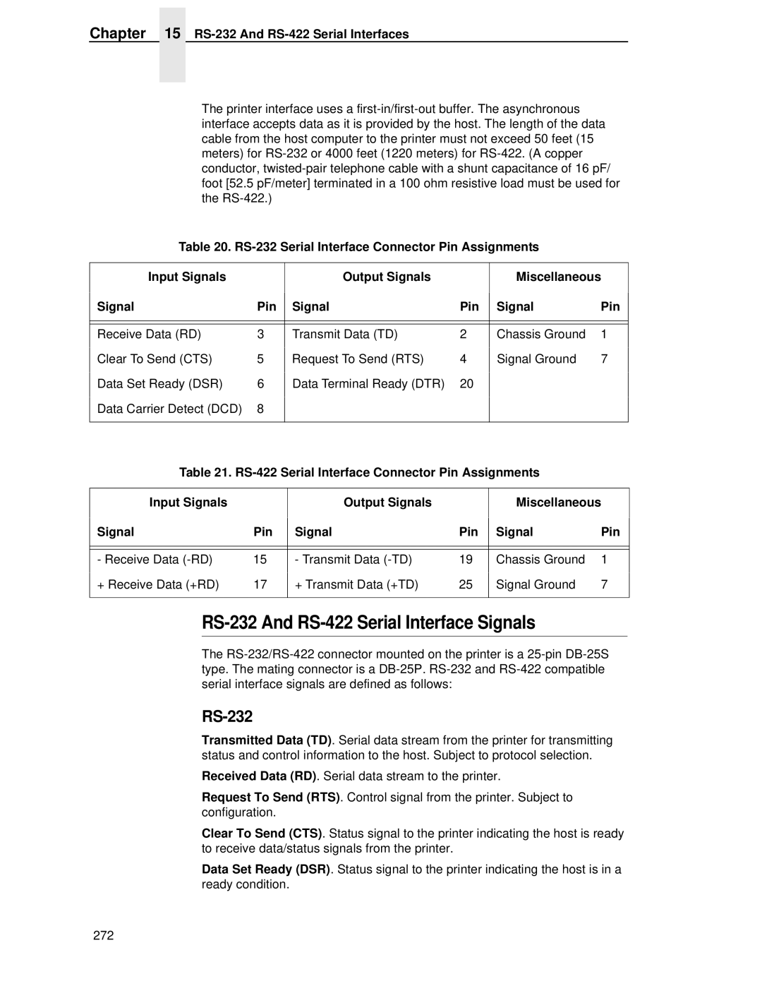
RS-232 And RS-422 Serial Interfaces
RS-232 And RS-422 Serial Interfaces
RS-232 And RS-422 Serial Interface Signals
RS-232
RS-232 And RS-422 Serial Interface Error Handling
RS-232 And RS-422 Serial Interface Protocol
RS-422
RS-232 And RS-422 Serial Interface Protocol
RS-232 only
RS-232 And RS-422 Serial Interface Configuration
RS-232 and RS-422
Routine Service Diagnostics
Routine Service
Exterior Cleaning
Interior Cleaning
Routine Service
Hammer bank. Only a trained service technician should clean
Shuttle assembly
Avoid damage
Interior Cleaning
Cleaning the Print Mechanism Cabinet Models
Diagnosing Problems
Diagnosing Problems
Printer Self-Tests
Sample Print Test All E’s Step Key Result
Printer Self-Tests Sample Print Test All E’s Step Key Result
= Full Width or 80 columns
Printing a Hex Dump
Hex Dump Sample
Printing a Hex Dump Step Key Result
Fault Messages
Fault Messages Requiring Field Service Attention
See Quick Reference Guide
Error DC
Error Writing
Reference Guide
PWR Supp Volt
Resetting
Stacker Fault
290
Printer Specifications Regulatory Information
Ribbon Specifications
Reference
Genuine Printronix P5000LJ Supplies
United States
Europe, the Middle East, and Africa
Asia Pacific
Printer Dimensions
Environmental Characteristics
Temperature
Appendix a Printer Dimensions
Electrical Characteristics
Energy Star
Material Safety Data Sheets
Appendix a Material Safety Data Sheets
Communication Notices
German Conformity Statement
Appendix a Communication Notices
299
300
Paper Specifications Forms Design
General Paper Specifications
Appendix B General Paper Specifications Paper Sizes
Paper Weights
Single-Part Forms
Multipart Forms
Terms And Definitions
Paper Guidelines
Terms And Definitions
Appendix B Paper Guidelines
Basic Forms Terminology
Form Weight
Environmental Considerations
Form Types
Form Thickness
Staples
Methods Of Forms Attachment
Gluing
Chaff Content
Chaff Content Preferred
Cut-To-Tie Ratio
Perforation Intersections
Form Design Checklist
Form Weight
Environment
Type Of Form
Chaff Content
Specification Inches Millimeters
Form Evenness
Tractor Pin Holes
Storage And Handling
Chaff Content
Summary
Storage
Storage And Handling
312
Standard Ascii Character Set
KEY
Appendix C
Monitoring Printers
Implementing Remote Management Software RMS
Agent/Manager Model
Standards of Network Printer MIBs
Appendix D Implementing Remote Management Software RMS
Components of the Printer MIB
Information Provided by the MIB
Monitoring With Web JetAdmin
Setting The Snmp Community Name
Monitoring Tools
Monitoring With AIX NetView/6000
Reference
Getting the Latest MIB Information
Ftp.isi.edu
Appendix D Monitoring Tools
Index
Page
Diagnostics PASSED, 42
Error Report
ILL Inst Accss Waiting for Ethernet Adapter Illgl OPR Accss
XX%, 43
Loading Program from Port XX%, 43
NDS
NIC
Page
Page
Page
Page
Page
Waiting for Ethernet Adapter
334
Page
173952-001