Output Conversion
Values transmitted by the TB have a status attached. The decision on what to do with each value is made by the Analog Input Function Block.
Device/ Input Simulation
The input can be a simulated value instead of a TB OUT value. This allows the AI block to be tested independently of the characteristics of the environment.
Fail-safe
•If the status of the Primary Value or Simulation Value is bad, the fault logic can output either the last usable measured value, or a given substitute value.
Device / Output Simulation
One of three settings can be selected. The result is the output parameter (OUT).
Setting | description | Output value |
AUTO | automatic | the |
|
|
|
MAN | manual | a |
|
|
|
O/S | function block disabled | the preset safety value. |
|
|
|
AIFB execution steps:
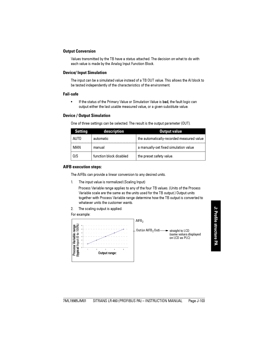
The AIFBs can provide a linear conversion to any desired units.
1.The input value is normalized (Scaling Input)
Process Variable range applies to any of the four TB values. (Units of the Process Variable scale are the same as the units used for the TB output.) Output units together with Process Variable range determine how the TB output is converted to whatever units the customer wants.
2.The scaling output is applied. For example:
range | 100%) | 6 |
|
|
|
|
5 |
|
|
|
| ||
4 |
|
|
|
| ||
Process Variable | (typical Input (0 to |
|
|
|
| |
3 |
|
|
|
| ||
2 |
|
|
|
| ||
1 |
|
|
|
| ||
0 |
|
|
|
| ||
1 | 2 | 3 | 4 | 5 | ||
|
| Output range: |
| |||
|
|
|
|
| ||
AIFB2 |
|
|
Out (or AIFB2 Out) |
| straight to LCD |
| ||
|
| (same values displayed |
|
| on LCD as PLC) |
J: Profile structure PA
7ML19985JM01 | SITRANS LR 460 (PROFIBUS PA) – INSTRUCTION MANUAL | Page |
