User’s Guide
Important Notice
Products Applications
Preface
Glossary
Register Bit Accessibility and Initial Condition
Register Bit Conventions
Page
Introduction
Basic Clock Module
Risc 16-Bit CPU
Flash Memory Controller
Supply Voltage Supervisor
Watchdog Timer
TimerA
Usart Peripheral Interface, SPI Mode
18 ADC10
Chapter
Architecture
Flexible Clock System
Embedded Emulation
−1. MSP430 Architecture
Flash/ROM
Address Space
2 RAM
Special Function Registers SFRs
Peripheral Modules
Memory Organization
6Introduction
Chapter
System Reset and Initialization
−1. Power-On Reset and Power-Up Clear Schematic
Power-On Reset POR
−2. POR Timing
Brownout Reset BOR
−3. Brownout Timing
Device Initial Conditions After System Reset
Software Initialization
Interrupts
−4. Interrupt Priority
Reset/NMI Pin
Non-Maskable Interrupts NMI
−5. Block Diagram of Non-Maskable Interrupt Sources
Flash Access Violation
Oscillator Fault
Example of an NMI Interrupt Handler
Maskable Interrupts
Interrupt Processing
Interrupt Acceptance
Return From Interrupt
Interrupt Nesting
Interrupt Vectors
−1. Interrupt Sources,Flags, and Vectors
Operating Modes
Mode CPU and Clocks Status
−10. MSP430x1xx Operating Modes For Basic Clock System
Entering and Exiting Low-Power Modes
Extended Time in Low-Power Modes
Connection of Unused Pins
Principles for Low-Power Applications
−2. Connection of Unused Pins
18System Resets, Interrupts, and Operating Modes
Chapter
CPU Introduction
−1. CPU Block Diagram
CPU Registers
Program Counter PC
Stack Pointer SP
−3. Stack Pointer
−1. Description of Status Register Bits
Status Register SR
Bit Description
Constant Generator − Expanded Instruction Set
Constant Generator Registers CG1 and CG2
−2. Values of Constant Generators CG1, CG2
Register Constant Remarks
General−Purpose Registers R4 R15
−7. Register -Byte/Byte-Register Operations
Addressing Modes
As/Ad Addressing Mode Syntax Description
−3. Source/Destination Operand Addressing Modes
−4. Register Mode Description
Register Mode
Assembler Code Content of ROM
Indexed Mode
−5. Indexed Mode Description
Symbolic Mode
−6. Symbolic Mode Description
Absolute Mode
−7. Absolute Mode Description
Indirect Register Mode
−8. Indirect Mode Description
Indirect Autoincrement Mode
−9. Indirect Autoincrement Mode Description
Immediate Mode
−10.Immediate Mode Description
Instruction Set
−11. Double Operand Instructions
Double-Operand Format I Instructions
Mnemonic Reg Operation Status Bits
Single-Operand Format II Instructions
−12.Single Operand Instructions
−13.Jump Instructions
Jumps
Mnemonic Reg, D-Reg Operation
ADC.W
ADC.B
ADD.W
ADD.B
ADDC.W
ADDC.B
AND.W
AND.B
BIC.W
BIC.B
BIS.W
BIS.B
BIT.W
BIT.B
BR, Branch
Call
CLR.B
Clrc
Clrn
Clrz
CMP.W
CMP.B
DADC.B
DADD.W
DADD.B
−12. Decrement Overlap
DEC.B
DECD.B
Disable Interrupt
Dint
Eint
Incd
INC.B
INCD.B
INV.B
JHS
JEQ, JZ
JGE
Jump if less
JMP
Hint
SUB R5,COUNT Count − R5 − Count
JNC
JLO
JNE
JNZ
MOV.W
MOV.B
NOP
POP.B
PUSH.W
PUSH.B
RET
−13. Main Program Interrupt
Reti
−14. Destination Operand-Arithmetic Shift Left
RLA.B
−15. Destination Operand-Carry Left Shift
RLC.B
RRA.W
RRA.B
RRC.W
RRC.B
SBC.B
Setc
Setn
Setz
SUB.W
SUB.B
Borrow Implementation
−18. Destination Operand Byte Swap
Swpb
−19. Destination Operand Sign Extension
SXT
TST.B
XOR.W
XOR.B
Format-II Single Operand Instruction Cycles and Lengths
Interrupt and Reset Cycles
Instruction Cycles and Lengths
Format-III Jump Instruction Cycles and Lengths
Format-I Double Operand Instruction Cycles and Lengths
−16.Format 1 Instruction Cycles and Lengths
Instruction Set Description
−20. Core Instruction Map
−17.MSP430 Instruction Set
Mnemonic Description
Page
Chapter
Basic Clock Module Introduction
−1. Basic Clock Block Diagram
Basic Clock Module Features for Low-Power Applications
Basic Clock Module Operation
−2. Off Signals for the LFXT1 Oscillator
LFXT1 Oscillator
Digitally-Controlled Oscillator DCO
3 XT2 Oscillator
Disabling the DCO
Adjusting the DCO frequency
−5. Typical DCOx Range and RSELx Steps
Using an External Resistor Rosc for the DCO
−6. DCO Frequency vs. Temperature
DCO Modulator
−7. Modulator Patterns
−9. Oscillator-Fault Signal
Basic Clock Module Fail-Safe Operation
Oscillator Fault Detection
−10. Oscillator-Fault-Interrupt
Sourcing Mclk from a Crystal
Synchronization of Clock Signals
−11. Switch Mclk from Dcoclk to LFXT1CLK
−1. Basic Clock Module Registers
Basic Clock Module Registers
Register Short Form Register Type Address Initial State
DCOCTL, DCO Control Register
BCSCTL1, Basic Clock System Control Register
DIVMx
BCSCTL2, Basic Clock System Control Register
SELMx
DIVSx
IE1, Interrupt Enable Register
IFG1, Interrupt Flag Register
18Basic Clock Module
Chapter
−1. Flash Memory Module Block Diagram
Flash Memory Introduction
Flash Memory Segmentation
−2. Flash Memory Segments, 4-KB Example
Flash Memory Operation
Flash Memory Timing Generator
Erasing Flash Memory
Erase Mode
−1. Erase Modes
Initiating an Erase from Within Flash Memory
−5. Erase Cycle from Within Flash Memory
Initiating an Erase from RAM
−6. Erase Cycle from Within RAM
−2. Write Modes
Write Mode
Writing Flash Memory
Byte/Word Write
Initiating a Byte/Word Write from Within Flash Memory
−8. Initiating a Byte/Word Write from Flash
Initiating a Byte/Word Write from RAM
−9. Initiating a Byte/Word Write from RAM
Block Write
−10. Block-Write Cycle Timing
Block Write Flow and Example
−11. Block Write Flow
KHz Smclk 952 kHz Assumes Accvie = Nmiie = Ofie =
Flash
Flash Memory Access During Write or Erase
−3. Flash Access While Busy =
Result
Flash Memory Controller Interrupts
Configuring and Accessing the Flash Memory Controller
Stopping a Write or Erase Cycle
Programming Flash Memory Devices
−12. User-Developed Programming Solution
Programming Flash Memory via Jtag
Flash Memory Registers
−4. Flash Memory Registers
Reserved
FCTL1, Flash Memory Control Register
Erase Cycle
FSSELx
FCTL2, Flash Memory Control Register
FWKEYx
FNx
FCTL3, Flash Memory Control Register FCTL3
Rather than MOV.B or CLR.B instructions
Flash Memory Controller
SVS Introduction SVS Operation SVS Registers
SVS Introduction
−1. SVS Block Diagram
SVS Operation
Configuring the SVS
SVS Comparator Operation
−2. Svson state When Changing VLDx
Changing the VLDx Bits
−3. Operating Levels for SVS and Brownout/Reset Circuit
SVS Operating Range
−1. SVS Registers
Read/write 055h Reset with BOR
SVS Registers
SVSCTL, SVS Control Register
Supply Voltage Supervisor
Chapter
−1. Hardware Multiplier Block Diagram
Hardware Multiplier Introduction
−1. OP1 addresses
Hardware Multiplier Operation
Operand Registers
OP1 Address Register Name Operation
Result Registers
−2. Reshi Contents
−3. Sumext Contents
Macs Underflow and Overflow
Software Examples
Process results
Using Interrupts
Indirect Addressing of Reslo
Hardware Multiplier Registers
−4. Hardware Multiplier Registers
Hardware Multiplier
DMA Introduction DMA Operation DMA Registers
DMA Introduction
−1. DMA Controller Block Diagram
DMA Operation
DMA Addressing Modes
DMA Transfer Modes
DMADTx Transfer Description Mode
−1. DMA Transfer Modes
Single Transfer
−3. DMA Single Transfer State Diagram
Block Transfers
−4. DMA Block Transfer State Diagram
Burst-Block Transfers
−5. DMA Burst-Block Transfer State Diagram
Level-Sensitive Triggers
Initiating DMA Transfers
Edge-Sensitive Triggers
Halting Executing Instructions for DMA Transfers
−2. DMA Trigger Operation
DMAxTSELx Operation
DMA Channel Priorities
Stopping DMA Transfers
DMA Priority Transfer Occurs New DMA Priority
DMA Transfer Cycle Time
CPU Operating Mode Clock Source Maximum DMA Cycle Time
−3. Maximum Single-Transfer DMA Cycle Time
Using DMA with System Interrupts
DMA Controller Interrupts
Using ADC12 with the DMA Controller
Using the I2C Module with the DMA Controller
Using DAC12 With the DMA Controller
DMA Registers
−4. DMA Registers
DMACTL0, DMA Control Register
TSELx
DMACTL1, DMA Control Register
DMAxCTL, DMA Channel x Control Register
Reserved DMADTx DMA DSTINCRx DMA SRCINCRx
DMAxSA, DMA Source Address Register
DMAxSAx
DMAxDA, DMA Destination Address Register
DMAxSZ, DMA Size Address Register
Page
Chapter
Digital I/O Introduction
Output Registers PxOUT
Digital I/O Operation
Input Register PxIN
Direction Registers PxDIR
Function Select Registers PxSEL
5 P1 and P2 Interrupts
Interrupt Flag Registers P1IFG, P2IFG
Configuring Unused Port Pins
Interrupt Enable P1IE, P2IE
Interrupt Edge Select Registers P1IES, P2IES
Digital I/O Registers
−1. Digital I/O Registers
Digital I/O
Watchdog Timer Operation 10-4
Watchdog Timer Introduction 10-2
Watchdog Timer Registers 10-7
Watchdog Timer Introduction
−1. Watchdog Timer Block Diagram
Watchdog Mode
Watchdog Timer Operation
Watchdog Timer Counter
Interval Timer Mode
Watchdog Timer Interrupts
Operation in Low-Power Modes
Watchdog Timer Registers
−1.Watchdog Timer Registers
WDTCTL, Watchdog Timer Register
WDTISx
Nmiie
Nmiifg
TimerA Operation 11-4
TimerA Introduction 11-2
TimerA Registers 11-19
TimerA Introduction
−1. TimerA Block Diagram
11.2.1 16-Bit Timer Counter
TimerA Operation
Clock Source Select and Divider
−1. Timer Modes
Starting the Timer
Timer Mode Control
MCx Mode Description
Up Mode
−2. Up Mode
Continuous Mode
−4. Continuous Mode
Use of the Continuous Mode
−6. Continuous Mode Time Intervals
Up/Down Mode
−7. Up/Down Mode
Use of the Up/Down Mode
−9. Output Unit in Up/Down Mode
Capture Mode
Capture/Compare Blocks
Compare Mode
−11. Capture Cycle
Output Modes
OUTMODx Mode Description
Output Unit
−2. Output Modes
−12.Output Example-Timer in Up Mode
−13.Output Example-Timer in Continuous Mode
−14.Output Example-Timer in Up/Down Mode
TACCR0 Interrupt
TimerA Interrupts
TAIV, Interrupt Vector Generator
Taiv Software Example
TimerA Registers
−3. TimerA Registers
TASSELx
TACTL, TimerA Control Register
Unused
IDx
TAR, TimerA Register
TARx
CCISx
TACCTLx, Capture/Compare Control Register
CMx
OUTMODx
TAIVx
TAIV, TimerA Interrupt Vector Register
Taiv Contents Interrupt Source Interrupt Flag Priority
Interrupt
11-24TimerA
TimerB Operation 12-4
TimerB Introduction 12-2
TimerB Registers 12-20
TimerB Introduction
Similarities and Differences From TimerA
−1. TimerB Block Diagram
12.2.1 16-Bit Timer Counter
TimerB Operation
TBR Length
−1.Timer Modes
Changing the Period Register TBCL0
Way as the other capture/compare registers
12-8TimerB
TBCL0−1 TBCL0 TBCL0−1 TBCL0−2
Changing the Value of Period Register TBCL0
−10. Capture Signal SCS=1
−11.Capture Cycle
−3.Compare Latch Operating Modes
TBCLGRPx Grouping Update Control
−2.TBCLx Load Events
CLLDx Description
−4.Output Modes
−12. Output Example-Timer in Up Mode
−13. Output Example-Timer in Continuous Mode
−14. Output Example-Timer in Up/Down Mode
TimerB Interrupts
TBIV, Interrupt Vector Generator
TBIV, Interrupt Handler Examples
TimerB Registers
−5.TimerB Registers
CNTLx
TimerB Control Register Tbctl
TBSSELx
TBR, TimerB Register
TBRx
TBCCTLx, Capture/Compare Control Register
CLLDx
12-24TimerB
Tbiv Contents Interrupt Source Interrupt Flag Priority
TBIV, TimerB Interrupt Vector Register
TBIVx
12-26TimerB
Usart Operation Uart Mode 13-4
Usart Introduction Uart Mode 13-2
Usart Registers Uart Mode 13-21
Usart Introduction Uart Mode
−1 shows the Usart when configured for Uart mode
−1. Usart Block Diagram Uart Mode
Usart Initialization and Reset
Usart Operation Uart Mode
Character Format
Asynchronous Communication Formats
Idle-Line Multiprocessor Format
13-6USART Peripheral Interface, Uart Mode
Address-Bit Multiprocessor Format
−4. Address -Bit Multiprocessor Format
−1.Receive Error Conditions
Automatic Error Detection
Error Condition Description
Usart Receive Enable
−5. State Diagram of Receiver Enable
Usart Transmit Enable
−6. State Diagram of Transmitter Enable
Uart Baud Rate Generation
−7. MSP430 Baud Rate Generator
Baud Rate Bit Timing
Determining the Modulation Value
Transmit Bit Timing
Brclk =
−9. Receive Error
Receive Bit Timing
Brclk
Typical Baud Rates and Errors
−2.Commonly Used Baud Rates, Baud Rate Data, and Errors
Usart Interrupts
Usart Transmit Interrupt Operation
Usart Receive Interrupt Operation
−11.Receive Interrupt Operation
Receive-Start Edge Detect Operation
−12. Glitch Suppression, Usart Receive Not Started
−3.USART0 Control and Status Registers
Usart Registers Uart Mode
−4.USART1 Control and Status Registers
UxCTL, Usart Control Register
UxTCTL, Usart Transmit Control Register
SSELx
UxRCTL, Usart Receive Control Register
UxBRx
UxMCTL, Usart Modulation Control Register
UxMCTLx
UxRXBUFx Bits
UxRXBUF, Usart Receive Buffer Register
UxTXBUF, Usart Transmit Buffer Register
UxTXBUFx Bits
ME1, Module Enable Register
ME2, Module Enable Register
IE2, Interrupt Enable Register
IFG2, Interrupt Flag Register
UTXIFG0 ‡
Usart Peripheral Interface, Uart Mode 13-31
Usart Operation SPI Mode 14-4
Usart Introduction SPI Mode 14-2
Usart Registers SPI Mode 14-13
Usart Introduction SPI Mode
−1. Usart Block Diagram SPI Mode
Usart Operation SPI Mode
Simo
Master Mode
Four-Pin SPI Master Mode
Slave Mode
Four-Pin SPI Slave Mode
SPI Enable
Transmit Enable
Receive Enable
−6. SPI Master Receive-Enable State Diagram
Serial Clock Control
−8. SPI Baud Rate Generator
Serial Clock Polarity and Phase
−9. Usart SPI Timing
SPI Interrupts
SPI Transmit Interrupt Operation
−12. Receive Interrupt State Diagram
SPI Receive Interrupt Operation
−1.USART0 Control and Status Registers
Usart Registers SPI Mode
−2.USART1 Control and Status Registers
I2C †
Ckph
Undefined
Baud-rate generator uses the content of UxBR1+UxBR0 to set
MSB is always reset
USPIE0 †
14-20USART Peripheral Interface, SPI Mode
USART0
14-22USART Peripheral Interface, SPI Mode
Usart Peripheral Interface, SPI Mode 14-23
2C Module Operation 15-4
2C Module Introduction 15-2
2C Module Registers 15-20
15.1 I2C Module Introduction
START/RESTART/STOP
−1. Usart Block Diagram I 2C Mode
−2. I 2C Bus Connection Diagram
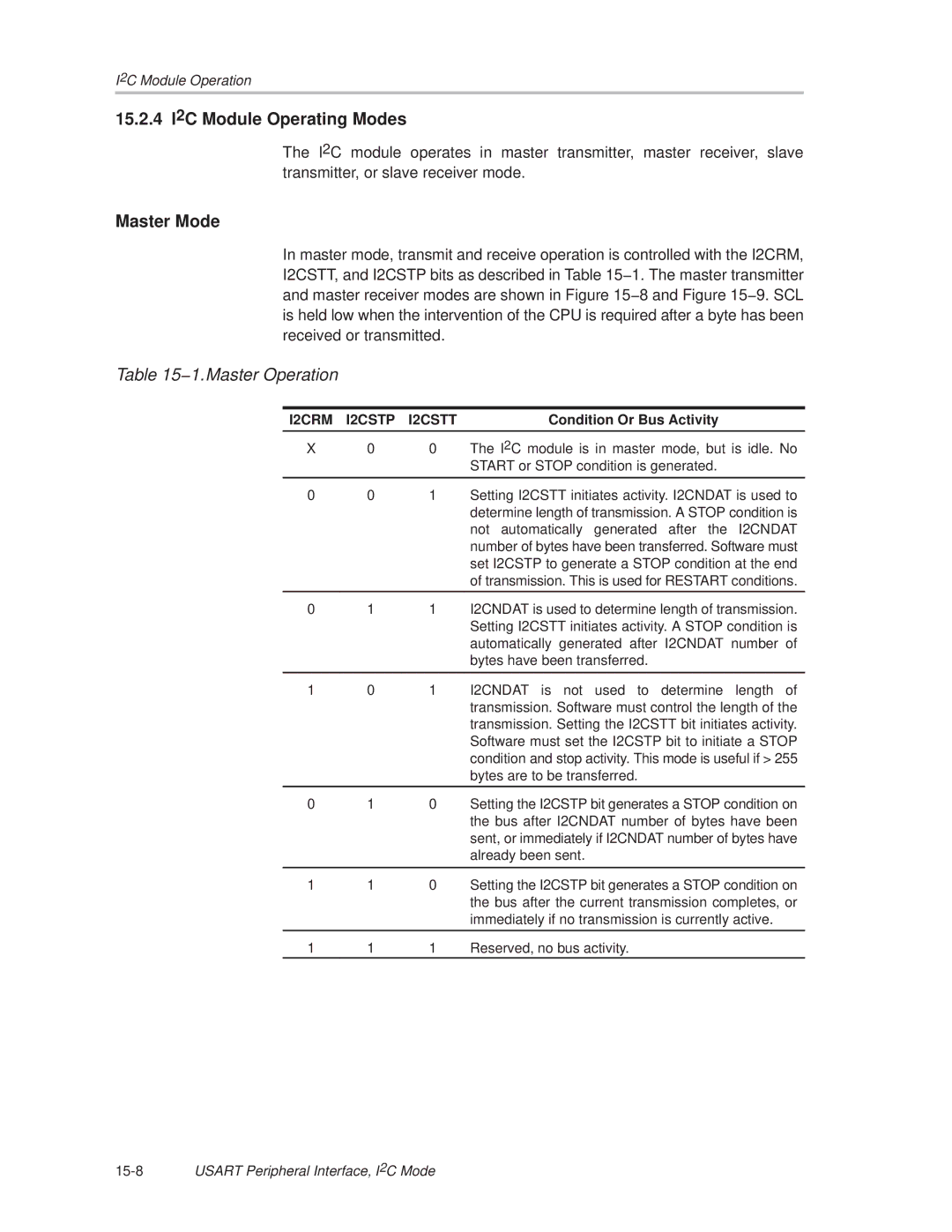
15.2 I2C Module Operation
15.2.1 I2C Module Initialization
15.2.2 I2C Serial Data
−3. I 2C Module Data Transfer
Bit Addressing
15.2.3 I2C Addressing Modes
Repeated Start Conditions
−1.Master Operation
15.2.4 I2C Module Operating Modes
Condition Or Bus Activity
−8. Master Transmitter Mode
−9. Master Receiver Mode
−10. Arbitration Procedure Between Two Master Transmitters
Automatic Data Byte Counting
−11.Slave Transmitter
−12. Slave Receiver
Transmit Underflow
I2C Data Register I2CDR
−2.I2CDR Register Function
Receive Overrun
15.2.6 I2C Clock Generation and Synchronization
−13. I 2C Module SCL Generation
Using the I2C Module with Low Power Modes
−3.I 2C Interrupts
15.2.8 I2C Interrupts
Interrupt Interrupt Condition Flag
I2CIV, Interrupt Vector Generator
I2CIV Software Example
15.3 I2C Module Registers
−4.I 2C Registers
U0CTL, USART0 Control Register-I2C Mode
I2CTCTL, I2C Transmit Control Register
I2CSSELx
I2CDCTL, I2C Data Control Register
I2CNDAT, I2C Transfer Byte Count Register
I2CDRW, I2CDRB, I2C Data Register
I2CNDATx Bits
I2CPSC, I2C Clock Prescaler Register
I2CPSCx
I2CSCLHx Bits
I2CSCLH, I2C Shift Clock High Register
I2CSCLL, I2C Shift Clock Low Register
I2CSCLLx Bits
I2COA, I2C Own Address Register, 10-Bit Addressing Mode
I2COA, I2C Own Address Register, 7-Bit Addressing Mode
I2COAx
I2CSA, I2C Slave Address Register, 10-Bit Addressing Mode
I2CSA, I2C Slave Address Register, 7-Bit Addressing Mode
I2CSAx
I2CIE, I2C Interrupt Enable Register
I2CIFG, I2C Interrupt Flag Register
I2CIV
I2CIV, I2C Interrupt Vector Register
I2CIVx
15-32USART Peripheral Interface, I2C Mode
ComparatorA Operation 16-4
ComparatorA Introduction 16-2
ComparatorA Registers 16-9
ComparatorA Introduction
−1. ComparatorA Block Diagram
ComparatorA Operation
Input Analog Switches
Comparator
Output Filter
Voltage Reference Generator
ComparatorA, Port Disable Register Capd
ComparatorA Interrupts
−5. Temperature Measurement System
ComparatorA Used to Measure Resistive Elements
−6. Timing for Temperature Measurement Systems
ComparatorA Registers
−1.ComparatorA Registers
CACTL1, ComparatorA Control Register
CACTL2, ComparatorA, Control Register
CAPD, ComparatorA, Port Disable Register
CAPDx
16-12ComparatorA
ADC12 Operation 17-4
ADC12 Introduction 17-2
ADC12 Registers 17-20
17.1 ADC12 Introduction
−1. ADC12 Block Diagram
17.2.1 12-Bit ADC Core
17.2 ADC12 Operation
Conversion Clock Selection
17.2.2 ADC12 Inputs and Multiplexer
Analog Port Selection
Auto Power-Down
Extended Sample Mode
Sample and Conversion Timing
Pulse Sample Mode
−4. Pulse Sample Mode
Sample Timing Considerations
−5. Analog Input Equivalent Circuit
Conversion Memory
−1.Conversion Mode Summary
CONSEQx Mode Operation
17.2.7 ADC12 Conversion Modes
Single-Channel Single-Conversion Mode
−6. Single-Channel, Single-Conversion Mode
Sequence-of-Channels Mode
−7. Sequence-of-Channels Mode
Repeat-Single-Channel Mode
−8. Repeat-Single-Channel Mode
Repeat-Sequence-of-Channels Mode
−9. Repeat-Sequence-of-Channels Mode
Using the Multiple Sample and Convert MSC Bit
Stopping Conversions
Using the Integrated Temperature Sensor
−10. Typical Temperature Sensor Transfer Function
17.2.9 ADC12 Grounding and Noise Considerations
−11.ADC12 Grounding and Noise Considerations
17.2.10 ADC12 Interrupts
ADC12IV, Interrupt Vector Generator
ADC12 Interrupt Handling Software Example
ADC12IFG15
17.3 ADC12 Registers
−2.ADC12 Registers
SHT1x
ADC12CTL0, ADC12 Control Register
SHT0x
Bit Reference generator voltage. Refon must also be set
SHSx
ADC12CTL1, ADC12 Control Register
ADDx
ADC12DIVx
Conversion
ADC12MEMx, ADC12 Conversion Memory Registers
CONSEQx
Results
SREFx
ADC12MCTLx, ADC12 Conversion Memory Control Registers
INCHx
ADC12IEx
ADC12IE, ADC12 Interrupt Enable Register
ADC12IFG, ADC12 Interrupt Flag Register
ADC12IFGx Bits
ADC12IV, ADC12 Interrupt Vector Register
Contents Interrupt Source Interrupt Flag Priority
ADC12IVx Bits
17-28 ADC12
ADC10 Operation 18-4
ADC10 Introduction 18-2
ADC10 Registers 18-24
18.1 ADC10 Introduction
−1. ADC10 Block Diagram
18.2 ADC10 Operation
18.2.1 10-Bit ADC Core
18.2.2 ADC10 Inputs and Multiplexer
Analog Port Selection
Internal Reference Low-Power Features
−3. Sample Timing
−4. Analog Input Equivalent Circuit
Conversion Modes
−5. Single-Channel Single-Conversion Mode
−6. Sequence-of-Channels Mode
−7. Repeat-Single-Channel Mode
−8. Repeat-Sequence-of-Channels Mode
Using the MSC Bit
18.2.7 ADC10 Data Transfer Controller
One-Block Transfer Mode
−9. One-Block Transfer
=0 ADC10DTC1 DTC reset Wait for write to
Two-Block Transfer Mode
−11.Two-Block Transfer
ADC10CT=1
DTC Transfer Cycle Time
CPU Operating Mode Clock Source Maximum DTC Cycle Time
Continuous Transfer
−2.Maximum DTC Cycle Time
−14. Typical Temperature Sensor Transfer Function
18.2.9 ADC10 Grounding and Noise Considerations
−16. ADC10 Grounding and Noise Considerations
18.2.10 ADC10 Interrupts
−17. ADC10 Interrupt System
18.3 ADC10 Registers
−3.ADC10 Registers
ADC10CTL0, ADC10 Control Register
SHTx
Bit Reference-generator voltage. Refon must also be set
ADC10CTL1, ADC10 Control Register
ADC10DIVx
ADC10AE, Analog Input Enable Control Register
ADC10AEx Bits
ADC10MEM, Conversion-Memory Register, Binary Format
ADC10MEM, Conversion-Memory Register, 2’s Complement Format
ADC10DTC0, Data Transfer Control Register
Transfers
ADC10DTC1, Data Transfer Control Register
ADC10SA, Start Address Register for Data Transfer
ADC10SAx
18-32 ADC10
DAC12 Operation 19-4
DAC12 Introduction 19-2
DAC12 Registers 19-10
19.1 DAC12 Introduction
−1. DAC12 Block Diagram
−1.DAC12 Full-Scale Range Vref = V eREF+ or VREF+
19.2 DAC12 Operation
19.2.1 DAC12 Core
DAC12 Port Selection
DAC12 Reference Input and Voltage Output Buffers
19.2.2 DAC12 Reference
Updating the DAC12 Voltage Output
19.2.4 DAC12xDAT Data Format
19.2.5 DAC12 Output Amplifier Offset Calibration
−4. Negative Offset
−6. DAC12 Group Update Example, TimerA3 Trigger
Grouping Multiple DAC12 Modules
19.2.7 DAC12 Interrupts
19.3 DAC12 Registers
−2.DAC12 Registers
DAC12xCTL, DAC12 Control Register
LSELx
DAC12AMPx Input Buffer Output Buffer
AMPx
DAC12 Data
DAC12xDAT, DAC12 Data Register
DAC12 Data Format
19-14 DAC12