www.ti.com | MDIO Registers |
4.2MDIO Control Register (CONTROL)
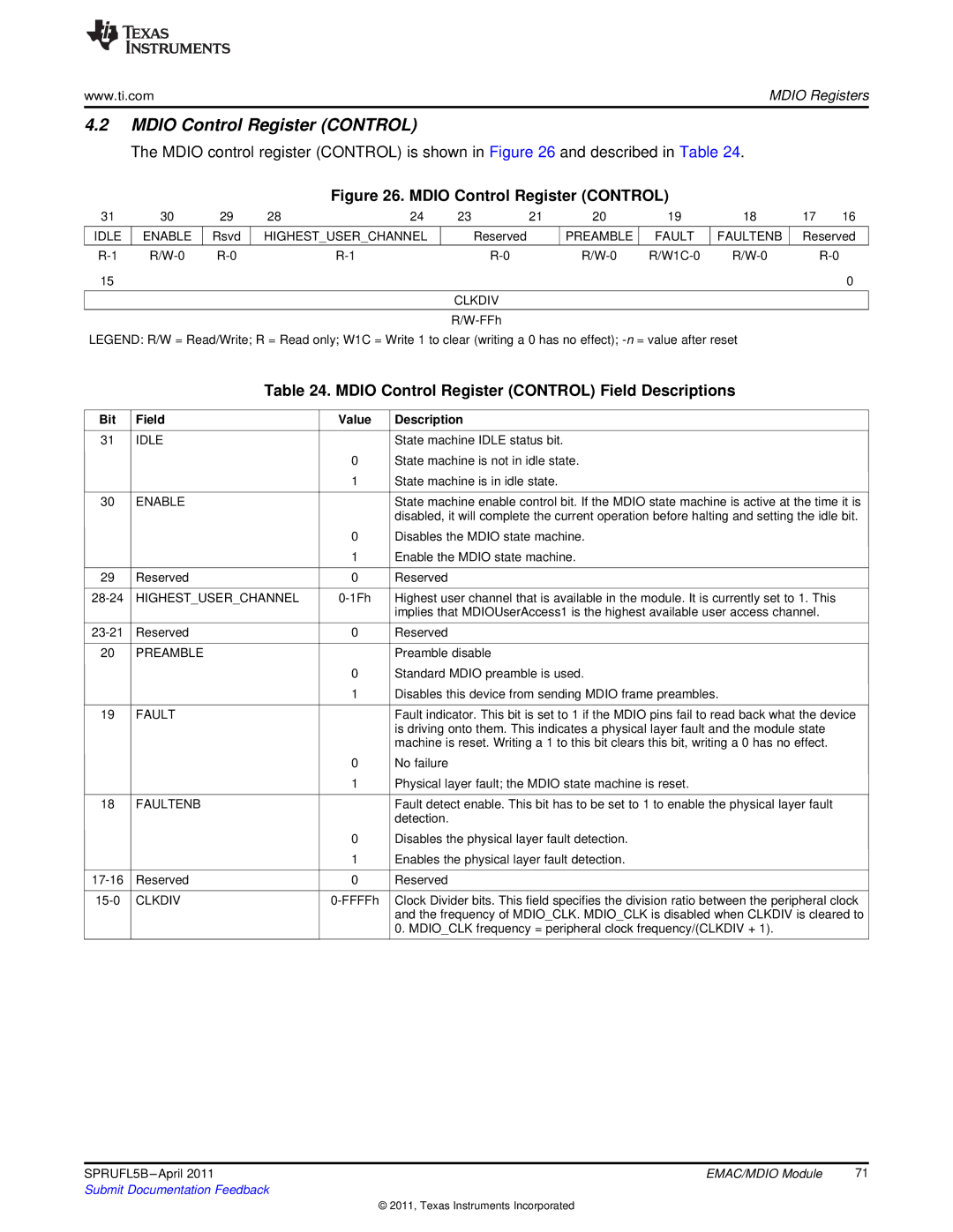
The MDIO control register (CONTROL) is shown in Figure 26 and described in Table 24.
Figure 26. MDIO Control Register (CONTROL)
31 | 30 | 29 | 28 | 24 | 23 | 21 | 20 | 19 | 18 | 17 | 16 |
IDLE | ENABLE | Rsvd | HIGHEST_USER_CHANNEL |
| Reserved | PREAMBLE | FAULT | FAULTENB | Reserved | ||
|
|
|
|
|
|
|
|
|
|
|
|
|
|
| |||||||||
15 |
|
|
|
|
|
|
|
|
|
| 0 |
CLKDIV
LEGEND: R/W = Read/Write; R = Read only; W1C = Write 1 to clear (writing a 0 has no effect);
Table 24. MDIO Control Register (CONTROL) Field Descriptions
Bit | Field | Value | Description |
|
|
|
|
31 | IDLE |
| State machine IDLE status bit. |
|
| 0 | State machine is not in idle state. |
|
| 1 | State machine is in idle state. |
|
|
|
|
30 | ENABLE |
| State machine enable control bit. If the MDIO state machine is active at the time it is |
|
|
| disabled, it will complete the current operation before halting and setting the idle bit. |
|
| 0 | Disables the MDIO state machine. |
|
| 1 | Enable the MDIO state machine. |
|
|
|
|
29 | Reserved | 0 | Reserved |
|
|
|
|
HIGHEST_USER_CHANNEL | Highest user channel that is available in the module. It is currently set to 1. This | ||
|
|
| implies that MDIOUserAccess1 is the highest available user access channel. |
|
|
|
|
Reserved | 0 | Reserved | |
|
|
|
|
20 | PREAMBLE |
| Preamble disable |
|
| 0 | Standard MDIO preamble is used. |
|
| 1 | Disables this device from sending MDIO frame preambles. |
|
|
|
|
19 | FAULT |
| Fault indicator. This bit is set to 1 if the MDIO pins fail to read back what the device |
|
|
| is driving onto them. This indicates a physical layer fault and the module state |
|
|
| machine is reset. Writing a 1 to this bit clears this bit, writing a 0 has no effect. |
|
| 0 | No failure |
|
| 1 | Physical layer fault; the MDIO state machine is reset. |
|
|
|
|
18 | FAULTENB |
| Fault detect enable. This bit has to be set to 1 to enable the physical layer fault |
|
|
| detection. |
|
| 0 | Disables the physical layer fault detection. |
|
| 1 | Enables the physical layer fault detection. |
|
|
|
|
Reserved | 0 | Reserved | |
|
|
|
|
CLKDIV | Clock Divider bits. This field specifies the division ratio between the peripheral clock | ||
|
|
| and the frequency of MDIO_CLK. MDIO_CLK is disabled when CLKDIV is cleared to |
|
|
| 0. MDIO_CLK frequency = peripheral clock frequency/(CLKDIV + 1). |
|
|
|
|
SPRUFL5B | EMAC/MDIO Module | 71 |
Submit Documentation Feedback |
|
|
© 2011, Texas Instruments Incorporated