www.ti.com
Clock Domains
4.2.3 DDR2/EMIF Clock
The DDR2 interface has a dedicated clock driven from PLL2. This is a separate clock system from the PLL1 clocks provided to other components of the system. This dedicated clock allows the reduction of the core clock rates to save power while maintaining the required minimum clock rate (125 MHZ) for DDR2. PLL2 must be configured to output a 2× clock to the DDR2 PHY interface.
The DM643x DMP video DACs are capable of driving high quality progressive television displays, if driven by a 54 MHZ input clock sourced by PLL2 (see the TMS320DM643x DMP Video Processing Back End (VPBE) User's Guide (SPRU952) for more detailed information). This will limit the possible PLL2 settings to a multiple of 54 MHZ so that the VPBE clock can be derived with a simple integer clock divider.
All of the following frequency ranges and multiplier/divider ratios in the
∙Input clock frequency range (MXI/CLKIN)
∙PLL2 multiplier (PLLM) range
∙PLL2 output (PLLOUT) frequency range based on core voltage (1.05V or 1.2V) of the device
Table
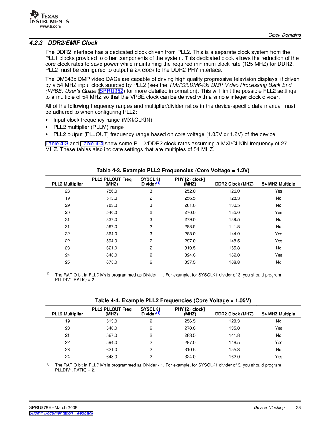
Table 4-3. Example PLL2 Frequencies (Core Voltage = 1.2V)
| PLL2 PLLOUT Freq | SYSCLK1 | PHY [2× clock] |
|
|
PLL2 Multiplier | (MHZ) | Divider(1) | (MHZ) | DDR2 Clock (MHZ) | 54 MHZ Multiple |
28 | 756.0 | 3 | 252.0 | 126.0 | Yes |
19 | 513.0 | 2 | 256.5 | 128.3 | No |
29 | 783.0 | 3 | 261.0 | 130.5 | No |
20 | 540.0 | 2 | 270.0 | 135.0 | Yes |
31 | 837.0 | 3 | 279.0 | 139.5 | No |
21 | 567.0 | 2 | 283.5 | 141.8 | No |
32 | 864.0 | 3 | 288.0 | 144.0 | Yes |
22 | 594.0 | 2 | 297.0 | 148.5 | Yes |
23 | 621.0 | 2 | 310.5 | 155.3 | No |
24 | 648.0 | 2 | 324.0 | 162.0 | Yes |
25 | 675.0 | 2 | 337.5 | 168.8 | No |
(1)The RATIO bit in PLLDIVn is programmed as Divider - 1. For example, for SYSCLK1 divider of 3, you should program PLLDIV1.RATIO = 2.
Table
| PLL2 PLLOUT Freq | SYSCLK1 | PHY [2× clock] |
|
|
PLL2 Multiplier | (MHZ) | Divider(1) | (MHZ) | DDR2 Clock (MHZ) | 54 MHZ Multiple |
19 | 513.0 | 2 | 256.5 | 128.3 | No |
20 | 540.0 | 2 | 270.0 | 135.0 | Yes |
21 | 567.0 | 2 | 283.5 | 141.8 | No |
22 | 594.0 | 2 | 297.0 | 148.5 | Yes |
23 | 621.0 | 2 | 310.5 | 155.3 | No |
24 | 648.0 | 2 | 324.0 | 162.0 | Yes |
(1)The RATIO bit in PLLDIVn is programmed as Divider - 1. For example, for SYSCLK1 divider of 3, you should program PLLDIV1.RATIO = 2.
Device Clocking | 33 |