www.ti.com
Boot Control
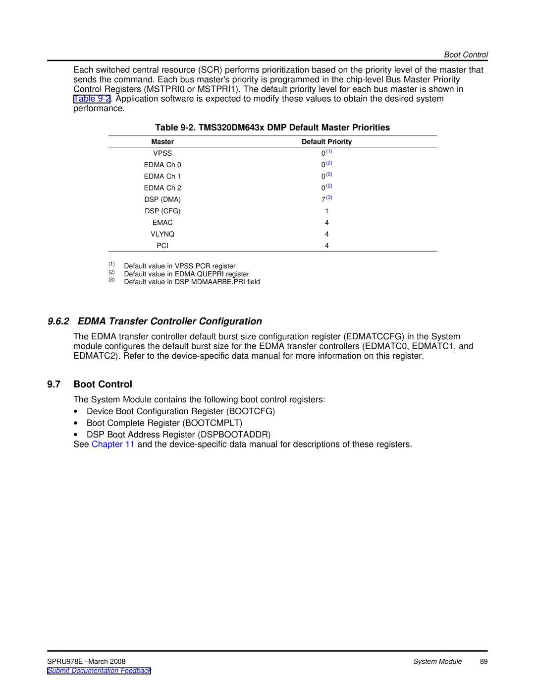
Each switched central resource (SCR) performs prioritization based on the priority level of the master that sends the command. Each bus master's priority is programmed in the
Table 9-2. TMS320DM643x DMP Default Master Priorities
Master | Default Priority |
VPSS | 0(1) |
EDMA Ch 0 | 0(2) |
EDMA Ch 1 | 0(2) |
EDMA Ch 2 | 0(2) |
DSP (DMA) | 7(3) |
DSP (CFG) | 1 |
EMAC | 4 |
VLYNQ | 4 |
PCI | 4 |
(1)Default value in VPSS PCR register
(2)Default value in EDMA QUEPRI register
(3)Default value in DSP MDMAARBE.PRI field
9.6.2EDMA Transfer Controller Configuration
The EDMA transfer controller default burst size configuration register (EDMATCCFG) in the System module configures the default burst size for the EDMA transfer controllers (EDMATC0, EDMATC1, and EDMATC2). Refer to the
9.7Boot Control
The System Module contains the following boot control registers:
∙Device Boot Configuration Register (BOOTCFG)
∙Boot Complete Register (BOOTCMPLT)
∙DSP Boot Address Register (DSPBOOTADDR)
See Chapter 11 and the
System Module | 89 |