6F8A0917
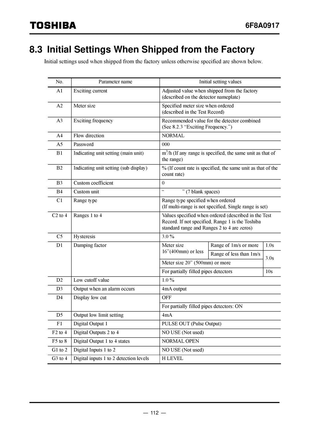
8.3 Initial Settings When Shipped from the Factory
Initial settings used when shipped from the factory unless otherwise specified are shown below.
No. | Parameter name |
| Initial setting values |
| |
|
|
|
|
| |
A1 | Exciting current | Adjusted value when shipped from the factory |
| ||
|
| (described on the detector nameplate) |
| ||
|
|
|
|
| |
A2 | Meter size | Specified meter size when ordered |
| ||
|
| (described in the Test Record) |
| ||
|
|
|
|
| |
A3 | Exciting frequency | Recommended value for the detector combined |
| ||
|
| (See 8.2.3 “Exciting Frequency.”) |
| ||
|
|
|
|
| |
A4 | Flow direction | NORMAL |
|
| |
|
|
|
|
|
|
A5 | Password | 000 |
|
|
|
|
|
|
|
| |
B1 | Indicating unit setting (main unit) | m3/h (If any range is specified, the same unit as that of | |||
|
| the range) |
|
| |
|
|
|
|
| |
B2 | Indicating unit setting (sub display) | % (If count rate is specified, the same unit as that of the | |||
|
| count rate) |
|
| |
|
|
|
|
|
|
B3 | Custom coefficient | 0 |
|
|
|
|
|
|
|
|
|
B4 | Custom unit | “ | ” (7 blank spaces) |
| |
|
|
|
|
| |
C1 | Range type | Range type specified when ordered |
| ||
|
| (If | |||
|
|
|
|
| |
C2 to 4 | Ranges 1 to 4 | Values specified when ordered (described in the Test | |||
|
| Record. If not specified, Range 1 is the Toshiba |
| ||
|
| standard range and Ranges 2 to 4 are zeros) |
| ||
|
|
|
|
|
|
C5 | Hysteresis | 3.0 % |
|
|
|
|
|
| Range of 1m/s or more |
| |
D1 | Damping factor | Meter size | 1.0s | ||
|
| 16”(400mm) or less | Range of less than 1m/s |
| |
|
| 3.0s | |||
|
|
|
| ||
|
| Meter size 20” (500mm) or more | |||
|
|
| |||
|
|
|
| ||
|
| For partially filled pipes detectors | 10s | ||
|
|
|
|
|
|
D2 | Low cutoff value | 1.0 % |
|
|
|
|
|
|
|
| |
D3 | Output when an alarm occurs | 4mA output |
|
| |
|
|
|
|
|
|
D4 | Display low cut | OFF |
|
|
|
|
|
|
| ||
|
| For partially filled pipes detectors: ON |
| ||
|
|
|
|
|
|
D5 | Output low limit setting | 4mA |
|
|
|
|
|
|
| ||
F1 | Digital Output 1 | PULSE OUT (Pulse Output) |
| ||
|
|
|
|
| |
F2 to 4 | Digital Outputs 2 to 4 | NO USE (Not used) |
|
| |
|
|
|
|
| |
F5 to 8 | Digital Output 1 to 4 states | NORMAL OPEN |
|
| |
|
|
|
|
| |
G1 to 2 | Digital Inputs 1 to 2 | NO USE (Not used) |
|
| |
|
|
|
|
| |
G3 to 4 | Digital inputs 1 to 2 detection levels | H LEVEL |
|
| |
|
|
|
|
|
|
