6F8A0917
10.9Converter Error Alarm Output
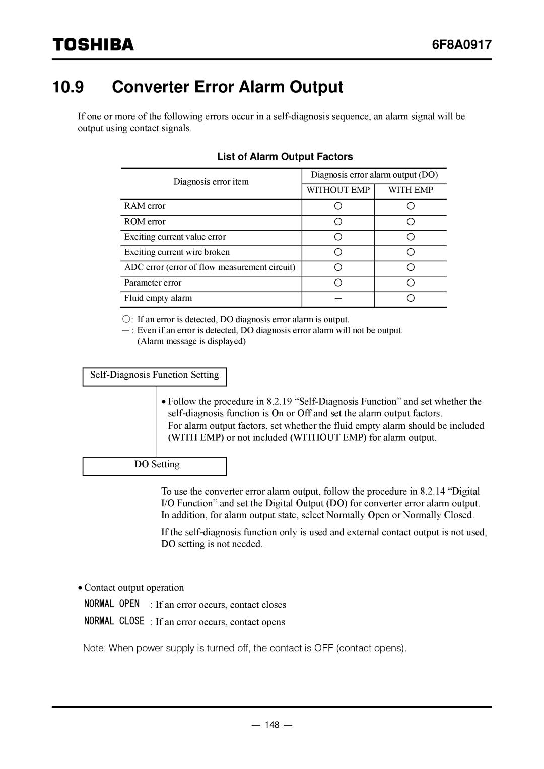
If one or more of the following errors occur in a
List of Alarm Output Factors
Diagnosis error item | Diagnosis error alarm output (DO) | ||
WITHOUT EMP | WITH EMP | ||
| |||
RAM error |
|
| |
ROM error |
|
| |
Exciting current value error |
|
| |
Exciting current wire broken |
|
| |
ADC error (error of flow measurement circuit) |
|
| |
Parameter error |
|
| |
Fluid empty alarm | − |
| |
○: If an error is detected, DO diagnosis error alarm is output.
−: Even if an error is detected, DO diagnosis error alarm will not be output. (Alarm message is displayed)
•Follow the procedure in 8.2.19
For alarm output factors, set whether the fluid empty alarm should be included (WITH EMP) or not included (WITHOUT EMP) for alarm output.
DO Setting
To use the converter error alarm output, follow the procedure in 8.2.14 “Digital
I/O Function” and set the Digital Output (DO) for converter error alarm output.
In addition, for alarm output state, select Normally Open or Normally Closed.
If the
DO setting is not needed.
•Contact output operation
NORMAL OPEN : If an error occurs, contact closes
NORMAL CLOSE : If an error occurs, contact opens
Note: When power supply is turned off, the contact is OFF (contact opens).
