6F8A0917
8. Parameter Settings / Adjustment
8.1 Parameter Setting Items
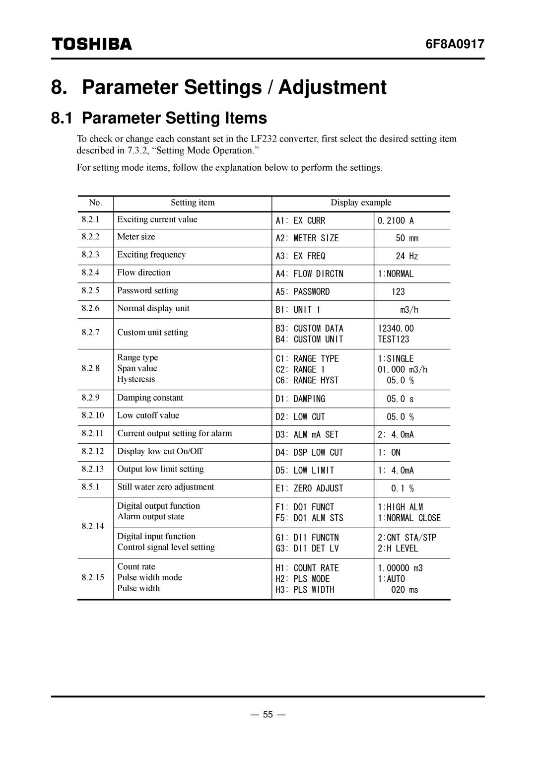
To check or change each constant set in the LF232 converter, first select the desired setting item described in 7.3.2, “Setting Mode Operation.”
For setting mode items, follow the explanation below to perform the settings.
No. | Setting item | Display example |
| ||
|
|
|
|
| |
8.2.1 | Exciting current value | A1: EX CURR | 0.2100 | A | |
|
|
|
|
| |
8.2.2 | Meter size | A2: METER SIZE | 50 | mm | |
|
|
|
|
| |
8.2.3 | Exciting frequency | A3: EX FREQ | 24 | Hz | |
|
|
|
| ||
8.2.4 | Flow direction | A4: FLOW DIRCTN | 1:NORMAL | ||
|
|
|
|
| |
8.2.5 | Password setting | A5: PASSWORD | 123 |
| |
|
|
|
| ||
8.2.6 | Normal display unit | B1: UNIT 1 | m3/h | ||
|
|
|
| ||
8.2.7 | Custom unit setting | B3: CUSTOM DATA | 12340.00 | ||
B4: CUSTOM UNIT | TEST123 |
| |||
|
|
| |||
|
|
|
| ||
8.2.8 | Range type | C1: RANGE TYPE | 1:SINGLE | ||
Span value | C2: RANGE 1 | 01.000 | m3/h | ||
| Hysteresis | C6: RANGE HYST | 05.0 | % | |
|
|
|
|
| |
8.2.9 | Damping constant | D1: DAMPING | 05.0 | s | |
|
|
|
|
| |
8.2.10 | Low cutoff value | D2: LOW CUT | 05.0 | % | |
|
|
|
| ||
8.2.11 | Current output setting for alarm | D3: ALM mA SET | 2: 4.0mA | ||
|
|
|
|
| |
8.2.12 | Display low cut On/Off | D4: DSP LOW CUT | 1: ON |
| |
|
|
|
| ||
8.2.13 | Output low limit setting | D5: LOW LIMIT | 1: 4.0mA | ||
|
|
|
|
| |
8.5.1 | Still water zero adjustment | E1: ZERO ADJUST | 0.1 | % | |
|
|
|
|
| |
| Digital output function | F1: DO1 FUNCT | 1:HIGH | ALM | |
8.2.14 | Alarm output state | F5: DO1 ALM STS | 1:NORMAL CLOSE | ||
|
|
|
| ||
Digital input function | G1: DI1 FUNCTN | 2:CNT STA/STP | |||
| |||||
| Control signal level setting | G3: DI1 DET LV | 2:H LEVEL | ||
|
|
|
| ||
8.2.15 | Count rate | H1: COUNT RATE | 1.00000 m3 | ||
Pulse width mode | H2: PLS MODE | 1:AUTO |
| ||
| Pulse width | H3: PLS WIDTH | 020 | ms | |
|
|
|
|
| |
- 55 -