6F8A0917
 Power cable, current output cable and digital I/O cables
Necessary cables should be purchased and prepared by the agent in charge of installation.
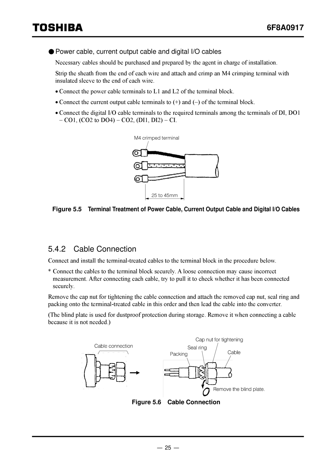
Strip the sheath from the end of each wire and attach and crimp an M4 crimping terminal with insulated sleeve to the end of each wire.
•Connect the power cable terminals to L1 and L2 of the terminal block.
•Connect the current output cable terminals to (+) and (−) of the terminal block.
•Connect the digital I/O cable terminals to the required terminals among the terminals of DI, DO1 − CO1, (CO2 to DO4) − CO2, (DI1, DI2) − CI.
M4 crimped terminal
25 to 45mm
Figure 5.5 Terminal Treatment of Power Cable, Current Output Cable and Digital I/O Cables
5.4.2Cable Connection
Connect and install the
*Connect the cables to the terminal block securely. A loose connection may cause incorrect measurement. After connecting each cable, try to pull it to check whether it has been connected securely.
Remove the cap nut for tightening the cable connection and attach the removed cap nut, seal ring and packing onto the
(The blind plate is used for dustproof protection during storage. Remove it when connecting a cable because it is not needed.)
Figure 5.6 Cable Connection
- 25 -
