6F8A0917
14. Principle of Operation
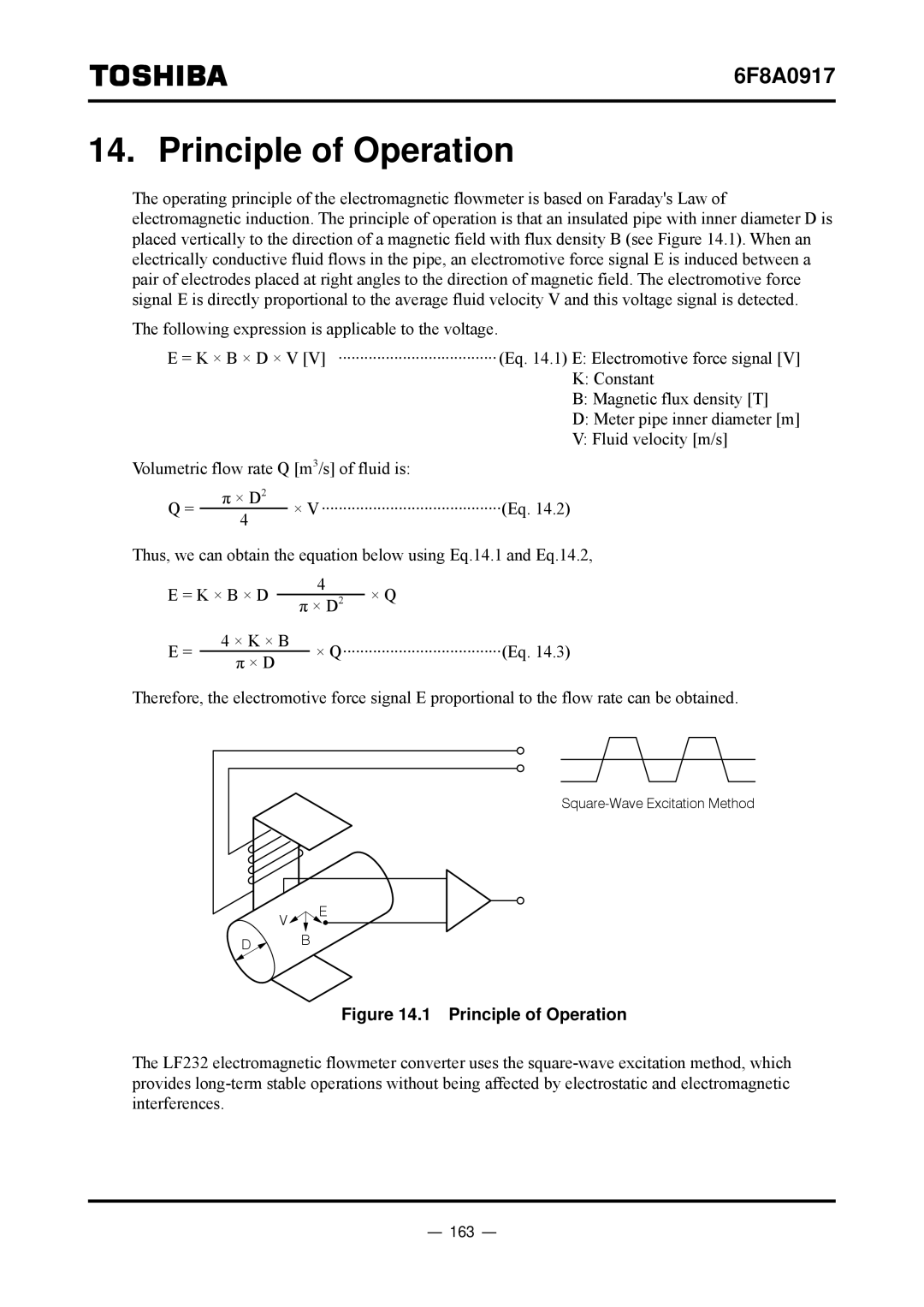
The operating principle of the electromagnetic flowmeter is based on Faraday's Law of electromagnetic induction. The principle of operation is that an insulated pipe with inner diameter D is placed vertically to the direction of a magnetic field with flux density B (see Figure 14.1). When an electrically conductive fluid flows in the pipe, an electromotive force signal E is induced between a pair of electrodes placed at right angles to the direction of magnetic field. The electromotive force signal E is directly proportional to the average fluid velocity V and this voltage signal is detected.
The following expression is applicable to the voltage.
E = K × B × D × V [V] ·····································(Eq. 14.1) E: Electromotive force signal [V] K: Constant
B: Magnetic flux density [T]
D: Meter pipe inner diameter [m]
V: Fluid velocity [m/s]
Volumetric flow rate Q [m3/s] of fluid is:
Q = | π × D2 | × V··········································(Eq. 14.2) | |
4 | |||
|
|
Thus, we can obtain the equation below using Eq.14.1 and Eq.14.2,
E = K × B × D |
| 4 | × Q | ||
| π × D2 | ||||
E = | 4 × K × B |
| × Q·····································(Eq. 14.3) | ||
π × D |
| ||||
|
|
|
| ||
Therefore, the electromotive force signal E proportional to the flow rate can be obtained.
V ![]()
![]() E
E
D ![]() B
B
Figure 14.1 Principle of Operation
The LF232 electromagnetic flowmeter converter uses the