6F8A0917
5.5 Digital I/O Connections
Digital I/O terminals consist of four contact output terminals (DO1 to DO4) and two voltage signal input terminals (DI1 and DI2), and each terminal is isolated from internal circuits.
The terminal CO2 is the signal common for DO2 to DO4 and the terminal CI is the signal common for DI1 and DI2. For details, see 10. “Function Description.”
The function of each terminal can be selected by settings. For details, see 10. “Function Description.”
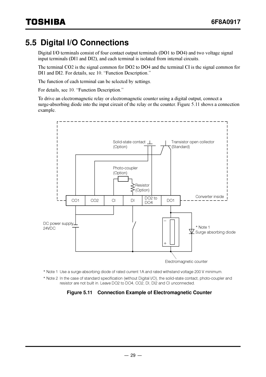
To drive an electromagnetic relay or electromagnetic counter using a digital output, connect a
Transistor open collector | |
(Option) | (Standard) |
Resistor (Option)
|
|
|
| DO2 to | Converter inside | |
CO1 | CO2 | CI | DI | DO1 | ||
DO4 | ||||||
|
|
|
|
|
DC power supply 24VDC
* Note 1
Surge absorbing diode
Electromagnetic counter
*Note 1 Use a
*Note 2 In the case of standard specification (without Digital I/O), the
Figure 5.11 Connection Example of Electromagnetic Counter
- 29 -